- Department of Neurosurgery and Brain Bank, Mihara Memorial Hospital, 366 Ohtemachi, Isesaki, Gunma, Japan.
DOI:10.25259/SNI-133-2019
Copyright: © 2019 Surgical Neurology International This is an open-access article distributed under the terms of the Creative Commons Attribution-Non Commercial-Share Alike 4.0 License, which allows others to remix, tweak, and build upon the work non-commercially, as long as the author is credited and the new creations are licensed under the identical terms.How to cite this article: Ryosuke Tomio. Effects of electrodes length and insulation for transcranial electric stimulation. 19-Jun-2019;10:111
How to cite this URL: Ryosuke Tomio. Effects of electrodes length and insulation for transcranial electric stimulation. 19-Jun-2019;10:111. Available from: http://surgicalneurologyint.com/surgicalint-articles/9373/
Date of Submission
17-Aug-2018
Date of Acceptance
02-May-2019
Date of Web Publication
19-Jun-2019
Abstract
Background: The aim of this study is to investigate the effects of length and insulation of the corkscrew electrodes for transcranial motor evoked potential (tMEP) monitoring.
Methods: We used the finite element method to visualize the electric field in the brain, which was generated by electrodes of different lengths (4, 7, and 12 mm). Two types of head models were generated: A model that included a subcutaneous fat layer and another without a fat layer. Two insulated needle types of conductive tip (5 and 2 mm) were studied. The stimulation threshold levels of hand tMEP were measured in a clinical setting to compare normal corkscrew and insulated 7-mm depth corkscrew.
Results: The electric field in the brain depended on the electrode depths in the no fat layer model. The deeper the electrodes reached, the stronger the electric fields generated. Electrode insulation made a difference in the fat layer models. The threshold level recordings of tMEP revealed that the 7-mm insulated electrodes showed a lower threshold than the normal electrodes by one-side replacement in each patient: 33.6 ± 9.6 mA and 36.3 ± 11.0 mA (n =16, P n =10, P = 0.003), respectively.
Conclusions: The electrodes depth reached enough to skull is considered to be efficient. Insulation of the electrodes with a conductive tip is efficient when there is subcutaneous fat layer.
Keywords: Corkscrew electrode, Insulation, Transcranial electric stimulation, Transcranial motor evoked potential
INTRODUCTION
Intraoperative motor evoked potentials (MEP) by transcranial electric stimulation (TES) are currently popular for motor function preservation.[
During TES with typical corkscrew electrodes, most of the current spreads laterally through the scalp due to the skull’s high resistance, only a small percentage (~20%) of the current seems to pass into the brain.[
The aim of this study is to identify the corkscrew electrode length and insulation design most effective at eliciting tMEP using a minimum stimulation current. To accomplish this, we investigated both the computer simulation by FE models and the stimulation threshold level of tMEP in a total of 26 clinical patients in a prospective study.
METHODS
Model simulation study
Realistic three-dimensional head model creation and electrode placement
The realistic three-dimensional (3D) head models created in this study were developed from international consortium for brain mapping T1-weighted images obtained from BrainWeb (http://brainweb.bic.mni.mcgill.ca/). The image processing and segmentation of 1 × 1 × 1 mm3 resolution images were done using ScanIP and+ScanFE (version 7.0, ©Simpleware Ltd., Exeter, United Kingdom). The brain, cerebrospinal fluid, skull, subcutaneous fat, and skin layer all were obtained from the T1-weighted images. These FE models meshed into more than 1.5 × 10⁷ tetrahedral elements (i.e., more than 1.5 × 10⁶ degrees of freedom) for the 1 × 1 × 1 mm3 resolution head models. Two types of head models were created. A model with all layers and another model which excluded the subcutaneous fat layer.
Corkscrew-type electrodes were created using computer-aided design (CAD) [
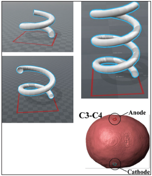
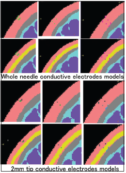
Figure 2
The coronal section of each needle depth (4 mm, 7 mm, and 12 mm) and two types of the three-dimensional head model (no fat layer model and all layers model) are shown. The upper six sections show the “whole needle conductive” type of the corkscrew needle, and the lower six sections show the “2-mm tip conductive” type of the needle.
Tissue conduction properties, calculations, and analyses by COMSOL Multiphysics
All tissue layers were modeled as homogeneous and isotropic with respect to electrical conductivity and permittivity based on data from the human organs property database for computing simulation (http://cfd-duo.riken.go.jp/cbms-mpindex.htm, Riken, Japan). The details of the conductivity values were the same as in our previous publication,[
The electric field distribution plotted on the coronal sections of the brain in each model was studied. Coronal sections containing both the electrodes and the motor cortex were made. The electric field values of brain section studies were visualized by a color scale with a range from 0 V/m (blue) to 60 V/m (red).
Limitations of the finite element models
The limitation details regarding the use of an isotropic layer, the direct current application mode by COMSOL Multiphysics, and a mesh generation are described in our previous publication.[
Clinical recordings of the transcranial motor evoked potential threshold
Two types of electrodes in recording and patient population
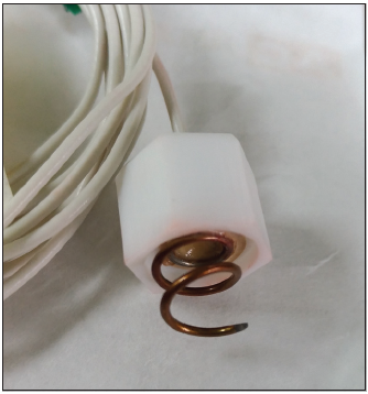
Intraoperative tMEP monitoring and recording of the stimulation threshold using the normal corkscrew and the order made corkscrew electrode were applied prospectively. The order made corkscrew electrode was designed to reach a depth of 7 mm under the skin, and the insulated needle had a 5-mm conductive tip [
The 16 patients for the one-side exchange consisted of 13 females and 3 males with an average age of 55.6 years (range was 37–75). The 10 patients for both sides exchange consisted of three females and seven males with an average age of 54.5 years (range was 43–66).
Neurophysiological monitoring methods and recording settings
The corkscrew electrode placements at C3 and C4 were based on the international 10–20 system. With the recordings of the one-side exchange method, recordings of the TES threshold level (mA) that elicits hand tMEP were performed with a normal corkscrew electrodes placement at both sides (C3 and C4), and the normal corkscrew electrode was replaced with an order made corkscrew at one side; then, the tMEP threshold level was recorded again to compare the difference of electrode types. For the recordings with both sides exchange method, the order made corkscrew electrodes were placed at both sides and the threshold was recorded; then, both electrodes were exchanged with the normal corkscrew before the next recording.
All recordings were performed before skin incision. We used an MEE-1200 series intraoperative monitoring system (Nihon Kohden Co., Ltd., Tokyo, Japan) as the electrophysiological device. Anodal electrical constant current stimulation was performed with short trains of 5 stimuli consisting of rectangular pulses with a pulse duration of 0.5 ms and an interstimulus interval of 2 ms. Compound muscle action potentials (CMAPs) of the abductor pollicis brevis were also recorded as tMEP. A bandpass filter was set from 30 to 3000 Hz. Stimulation threshold was judged as a level of stimulation current (mA) that constantly elicits CMAPs of >50 μV. We limited the maximum stimulation to 100 mA for safety because high stimulation levels often cause excessive muscle contraction of the head and neck by the lateral current and can stress the patient under head-pin fixation. Analysis of the data by t-test was performed with SPSS statistics 21 (IBM Corp). Moreover, clinical data recording of this study was in accordance with the ethical standards of the IRB of Keio University and with the Helsinki Declaration of 1975, as revised in 2000 and 2008. Informed consent of neurophysiologic monitoring was also obtained before surgery.
Anesthesia
Anesthesia was induced with a bolus of propofol and remifentanil, and maintained with propofol and remifentanil at average dosage. A short-acting muscle relaxant was induced as a bolus for intubation purposes. Although we did not use the “train of 4 stimuli” technique to test the level of relaxation due to time constraints before surgery, we routinely used neostigmine as a reversal agent for muscle relaxation after intubation and before the recording of the tMEP threshold.
RESULTS
Electric field distribution for each electrode type in the finite element models
The electric fields in all three needle depths and three insulation designs were studied at the 1 × 1 × 1 mm3 resolution no fat layer head models and are shown using the coronal sections [
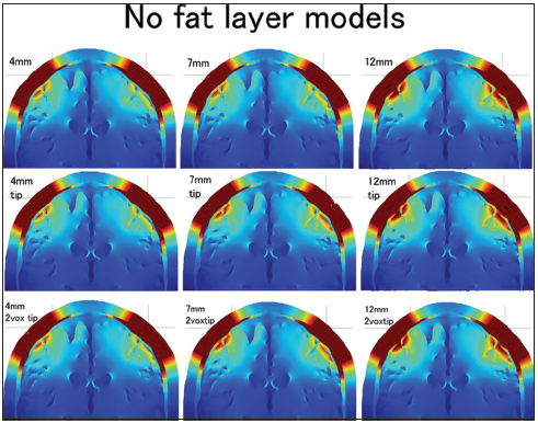
Figure 4
The distributions of the electric field for three electrode lengths (4 mm, 7 mm, and 9 mm) and three types of conductive tip length (whole needle conductive, 5-mm tip conductive, and 2-mm tip conductive) in the no fat layer head models are shown in 3 × 3 (from the left: 4-mm, 7-mm, and 9-mm depth; from the top: Whole needle conductive, 5-mm tip conductive, and 2-mm tip conductive). The color scale ranges from 0 V/m (blue) to 60 V/m (red).
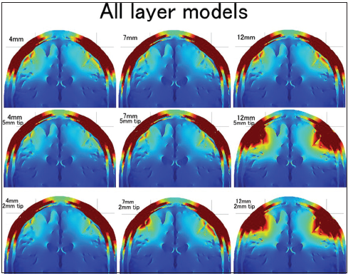
Figure 5
The distributions of the electric field for three electrode lengths (4 mm, 7 mm, and 9 mm) and three types of conductive tip length (whole needle conductive, 5-mm tip conductive, and 2-mm tip conductive) in the all layers head models are shown in 3 × 3 (from the left: 4-mm, 7-mm, and 9-mm depth; from the top: Whole needle conductive, 5-mm tip conductive, and 2-mm tip conductive). The color scale ranges from 0 V/m (blue) to 60 V/m (red).
The electric field distribution of the superficial skin layer should also be addressed in this study. The distribution was always almost the same in the no fat layer head models regardless of the needle type. However, the distribution of the superficial skin layer was changed by the needle depth and insulation in the all layers head models. The distribution was narrow in the 12-mm insulated needle models. The 7-mm insulated needle with a 2-mm conductive tip also showed a slightly narrower electric field distribution in the superficial skin layer.
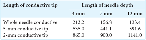
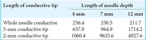
The conductive resistance values (Ω) were also calculated in each model of no fat layer head models [
Threshold change of transcranial motor evoked potential stimulation between the normal and order made electrode in patients
The order made electrode cases showed a lower tMEP threshold, on average, than the normal electrode cases, which achieved statistical significance in the comparison of 16 patients for the one-side exchange method (33.6 ± 9.6 mA and 36.3 ± 11 mA, respectively) (paired t-test, n = 16, P < 0.001). The order made electrode showed an approximately 7.4% lower threshold, on average.
Ten patients for both sides exchange also showed a lower threshold with order made electrode cases than for the normal electrode cases (34.4 ± 8.6 mA and 37.5 ± 9.2 mA, respectively) (paired t-test, n = 10, P = 0.003). The order made electrode showed an approximately 8.3% lower threshold, on average, in both sides exchange.
DISCUSSION
Needle depth
The 3D head model study confirmed a positive effect for needle elongation in most of the all layers head models and the no fat layer head models, with or without needle insulation. The positive effect of needle elongation for generating a higher electric field in the brain seems to be very instinctive for us, because the deeper the needle tip reached, the shorter the distance between the needle tip and the brain. Watanabe et al. reported the effectiveness of the peg-screw electrodes, which stick into the skull to generate a higher electric field in the brain during TES. Although the corkscrew electrodes cannot run into the skull, and the needle tip is always in the skin or fat layer, our results for the 3D head model study showed an advantage for corkscrew needle elongation. One of the riddles of our results was that the 4-mm no insulation needle model showed a slightly higher electric field than the 7-mm no insulation needle model on the all layers head. The difference between these two models was the location of the electrode tip [
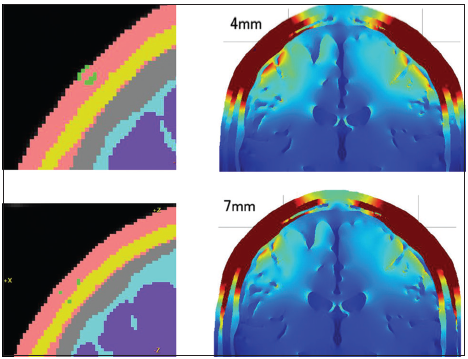
Figure 6
The coronal section of the 4-mm and 7-mm depth whole needle conductive corkscrew and its distributions of the electric fields in the brain are shown. One of the riddles of our results was that the 4-mm no insulation needle model showed a slightly higher electric field than the 7-mm no insulation needle model on the all layers head. The difference between these two models was the location of the electrode tip. The 4-mm corkscrew needle located in the skin layer. The 7-mm corkscrew needle reached the subcutaneous fat layer.
Needle insulation
The result of studying needle insulation using the 3D head model was that needle insulation had a positive effect if the head model included a high impedance subcutaneous fat layer and the conductive part of the needle penetrated the fat layer. Neurosurgeons know that all patients have subcutaneous fat in the scalp, but individual differences are quite large on an empirical basis. The effect of needle insulation should depend on the patient’s body type. If a patient has an apparent subcutaneous fat layer, the insulated deep corkscrew needle should be effective.
The insulated needle models showed maximum effect when the needle depth was 12 mm. Actually, the 12-mm depth insulated needle models had the highest electric field distribution in the brain among all the models. On the other hand, the insulated 4-mm depth electrode had a lower electric field in the brain than the 4-mm noninsulated electrode. This result coincided with our previous clinical study findings, that is, the order made 4-mm insulated corkscrew electrode showed no advantage in tMEP ignition than the normal corkscrew electrode (not published). The 3D head model study showed that needle insulation was effective if the conductive tip reached the high impedance subcutaneous fat layer. A dissimilarity between the 12-mm and 7-mm needle depth in these models was that the 12-mm needle depth penetrated the fat layer, but the 7-mm needle depth tip located in the fat layer and did not penetrate the fat. This penetration seemed to make a large difference between the 7-mm and 12-mm depths. The effect of needle insulation was apparent in the 12-mm needle models; however, there was no electric field distribution difference between the two types of 12-mm needle insulation designs. These results suggest that the locational relationship between the conductive part of the needle and the subcutaneous layer of the model is quite important for the electric field in the brain. If the location of the conductive part was limited to the subcutaneous fat layer and the skin layer under the fat, the electric field in the brain became quite high. The conductive resistance values and voltage between the anode and cathode were high in such models. On the other hand, the electric field in the brain was lower when the location of the conductive part included the superficial skin layer. The electric field distribution of the superficial skin layer was lower and narrower when the location of the conductive part was deeper than the subcutaneous fat layer. The difference in electric field distribution between the 5-mm conductive tip and the 2-mm conductive tip of a 7-mm depth insulated needle also depends on the location of the conductive tip [
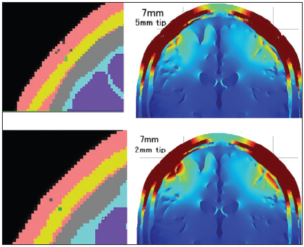
Figure 7
The coronal section of the 2-mm tip and 5-mm tip conductive 7 mm depth insulated needle corkscrew and its distributions of the electric fields in the brain are shown. The 2-mm conductive tip located in the fat layer; however, the 5-mm conductive tip contacted both the superficial skin layer and the fat layer so that the 2-mm conductive tip model generated a higher electric field in the brain.
One problem with needle insulation is that needle insulation always increases conductive resistance and it needs higher electric voltage during constant current stimulation of tMEP. The intraoperative monitoring system usually has voltage limitation. For example, the voltage limitation of our intraoperative monitoring system (MEE-1200) is 200 V, and if the resistance is quite high, it cannot apply given amount of electric current. Thus, an insulated needle with inadequately high conductive resistance inhibits adequate tMEP monitoring with constant current stimulation in real clinical setting.
Effectiveness of the order made electrode for the clinical case
The order made electrode was designed to have a 7-mm depth insulated needle. The conductive part of the needle was a 5-mm long tip. This needle tip reached to the skull in all cases, and the conductive tip was designed to locate deeper than the subcutaneous fat. In fact, cases with the order made electrode showed a lower threshold than the normal electrode, with a statistically significant difference. The threshold difference, on average, between the order made electrode and the normal commercially used electrode was <10%. This percentage value was lower than expected by the FEM analysis using 3D head models in this study. The all layers head model study with an insulated 12-mm depth corkscrew showed a quite high electric field distribution in the brain than for 4-mm depth no insulation needle models; however, the result of threshold change in clinical cases was not drastic. This dissociation between the model study result and the clinical threshold change could be caused by dissociation between the 3D head model and actual human head in their conductivity properties. The all layers head model made by T1 MRI sequences in this study included the high electric resistance isotropic subcutaneous fat layer, acting like a thin wall for electric current. Existence of this high impedance fat layer in the 3D head model could cause the dissociation of the results. An actual human head includes subcutaneous fat in most of the cases, but it would not be isotropic and may not have high resistance because there would be many conductive tissues such as vessels penetrating the fat layer. The human head may be more similar to the no fat layer model than the all layers head model. If a patient’s head is similar to the no fat layer model, the electric field distribution results of the no fat model study seem to be consistent with the threshold change results in clinical cases, and needle depth elongation may be more effective to generate a higher electric field in the brain than the needle insulation. On the other hand, if a patient’s head includes a thick isotropic subcutaneous fat layer under the skin, the needle insulation should be effective. Individual differences in body type should affect the effectiveness of needle insulation. Further study is needed to establish the most effective design of the corkscrew needle in an actual human head to generate a higher electric field in the brain.
The order made corkscrew electrode was superior to the normal corkscrew electrode in eliciting tMEP effectively, but difference between these two types was approximately 8% in this study. Advantage of the order made corkscrew electrode was substantially equal in both the one-side exchange and both sides exchange method. This 8% difference of the threshold value of electric current was not large, but it would be meaningful in tMEP of head muscle monitoring, especially in facial and lower cranial nerve-related muscles. A disadvantage of such cranial nerve tMEP is its difficulty in accurate recording due to both contractions by the lateral spread of electric current and artifact waves during TES. A decreased level of electric stimulation current can reduce both the lateral spread and artifacts. Not only did the order made corkscrew electrode reduce the threshold level of TES but also the FEM study of the 3D head model also showed that insulation of the needle can directly reduce the lateral spread in the skin layer. These two advantages of the order made corkscrew could improve the accuracy of facial and lower cranial nerve tMEP. Further, clinical study of cranial nerve tMEP with the order made corkscrew electrode is needed to prove its efficacy and superiority to the normal corkscrew electrode.
CONCLUSIONS
The 3D head model study with FEM showed that needle elongation can generate a higher electric field in the brain. The needle insulation was effective when the conductive tip of the needle reached and penetrated the high impedance subcutaneous fat layer in the model study. The insulation can generate a higher electric field in the brain and reduce the lateral spread in the skin layer. On the other hand, if there is no subcutaneous fat layer, the needle insulation was not effective.
The order made corkscrew electrode (7-mm depth and insulated) showed an approximately 8% reduced upper extremity tMEP threshold electric current level than the normal commercially used corkscrew electrodes. This order made corkscrew electrode could be effective, especially in cranial nerve tMEPs.
Financial support and sponsorship
Nil.
Conflicts of interest
There are no conflicts of interest.
Acknowledgments
This work was supported by JSPS KAKENHI Grant Number 18K16576.
We thank Keisoku Engineering, Tokyo, for their contributions to technical support of COMSOL Multiphysics.
References
1. Holdefer RN, Sadleir R, Russell MJ. Predicted current densities in the brain during transcranial electrical stimulation. Clin Neurophysiol. 2006. 117: 1388-97
2. Miranda PC, Mekonnen A, Salvador R, Ruffini G. The electric field in the cortex during transcranial current stimulation. Neuroimage. 2013. 70: 48-58
3. Stecker MM. Transcranial electric stimulation of motor pathways: A theoretical analysis. Comput Biol Med. 2005. 35: 133-55
4. Szelényi A, Hattingen E, Weidauer S, Seifert V, Ziemann U. Intraoperative motor evoked potential alteration in intracranial tumor surgery and its relation to signal alteration in postoperative magnetic resonance imaging. Neurosurgery. 2010. 67: 302-13
5. Szelényi A, Kothbauer KF, Deletis V. Transcranial electric stimulation for intraoperative motor evoked potential monitoring: Stimulation parameters and electrode montages. Clin Neurophysiol. 2007. 118: 1586-95
6. Szelényi A, Langer D, Kothbauer K, De Camargo AB, Flamm ES, Deletis V. Monitoring of muscle motor evoked potentials during cerebral aneurysm surgery: Intraoperative changes and postoperative outcome. J Neurosurg. 2006. 105: 675-81
7. Tomio R, Akiyama T, Horikoshi T, Ohira T, Yoshida K. Visualization of the electric field evoked by transcranial electric stimulation during a craniotomy using the finite element method. J Neurosci Methods. 2015. 256: 157-67
8. Tomio R, Akiyama T, Ohira T, Yoshida K. Comparison of effectiveness between cork-screw and peg-screw electrodes for transcranial motor evoked potential monitoring using the finite element method. Surg Neurol Int. 2016. 7: S791-6
9. Tomio R, Akiyama T, Ohira T, Yoshida K. Effects of transcranial stimulating electrode montages over the head for lower-extremity transcranial motor evoked potential monitoring. J Neurosurg. 2017. 126: 1951-8
10. Tomio R, Akiyama T, Toda M, Ohira T, Yoshida K. The impact of several craniotomies on transcranial motor evoked potential monitoring during neurosurgery. J Neurosurg. 2017. 127: 543-52
11. Watanabe K, Watanabe T, Takahashi A, Saito N, Hirato M, Sasaki T. Transcranial electrical stimulation through screw electrodes for intraoperative monitoring of motor evoked potentials. Technical note. J Neurosurg. 2004. 100: 155-60
12. Zhou Q, Zhang M, Jiang Y. Intraoperative oculomotor nerve monitoring predicts outcome following clipping of posterior communicating artery aneurysms. J Clin Neurosci. 2012. 19: 706-11