- Department of Neurosurgery, Tokuda Hospital, Sofia, Bulgaria
Correspondence Address:
Toma Spiriev
Department of Neurosurgery, Tokuda Hospital, Sofia, Bulgaria
DOI:10.4103/sni.sni_419_16
Copyright: © 2017 Surgical Neurology International This is an open access article distributed under the terms of the Creative Commons Attribution-NonCommercial-ShareAlike 3.0 License, which allows others to remix, tweak, and build upon the work non-commercially, as long as the author is credited and the new creations are licensed under the identical terms.How to cite this article: Toma Spiriev, Vladimir Nakov, Lili Laleva, Christo Tzekov. OsiriX software as a preoperative planning tool in cranial neurosurgery: A step-by-step guide for neurosurgical residents. 10-Oct-2017;8:241
How to cite this URL: Toma Spiriev, Vladimir Nakov, Lili Laleva, Christo Tzekov. OsiriX software as a preoperative planning tool in cranial neurosurgery: A step-by-step guide for neurosurgical residents. 10-Oct-2017;8:241. Available from: http://surgicalneurologyint.com/?post_type=surgicalint_articles&p=8633
Date of Submission
27-Oct-2016
Date of Acceptance
06-Jun-2017
Date of Web Publication
10-Oct-2017
Abstract
Background:OsiriX (Pixmeo, Switzerland) is an open-source Digital Imaging and Communications in Medicine (DICOM) viewer that is gaining more and more attention in the neurosurgical community because of its user-friendly interface, powerful three-dimensional (3D) volumetric rendering capabilities, and various options for data integration. This paper presents in detail the use of OsiriX software as a preoperative planning tool in cranial neurosurgery.
Methods:In January 2013, OsiriX software was introduced into our clinical practice as a preoperative planning tool. Its capabilities are being evaluated on an ongoing basis in routine elective cranial cases.
Results:The program has proven to be highly effective at volumetrically representing data from radiological examinations in 3D. Among its benefits in preoperative planning are simulating the position and exact location of the lesion in 3D, tailoring the skin incision and craniotomy bone flap, enhancing the representation of normal and pathological anatomy, and aiding in planning the reconstruction of the affected area.
Conclusion:OsiriX is a useful tool for preoperative planning and visualization in neurosurgery. The software greatly facilitates the surgeon's understanding of the relationship between normal and pathological anatomy and can be used as a teaching tool.
Keywords: Intracranial aneurysms, meningioma, neurooncology, OsiriX software, preoperative planning in neurosurgery, simulation
INTRODUCTION
Correct and detailed preoperative planning is one of the most important prerequisites of successful surgery and is a skill that takes years to master and understand. The difficulty comes from transforming the two-dimensional preoperative radiological black-and-white data into a three-dimensional (3D) image in the surgeon's mind, a view that represents the surgical position of the patient, the small cranial exposure, and the distortion of the normal anatomy caused by the lesion. This process of transforming the data is most difficult at the beginning of one's career in early residency.
Fortunately, modern-day technology provides multiple aids in this regard: sophisticated neuronavigation systems, dedicated software for preoperative planning and simulation, the software of the internal workstation in the radiological department, and modern simulation technology.[
By contrast, OsiriX is an open-source Digital Imaging and Communications in Medicine (DICOM) viewer with the powerful capability of 3D volumetric rendering. OsiriX has gained significant attention in recent years as a tool of research in neurosurgery;[
Aim
The aim of this paper is to present the experience of using OsiriX software as a preoperative planning tool in cranial neurosurgery. The technique used for planning the surgical simulation of the patient positioning, skin incision, tailoring of the bone flap, and exposure of the lesion is discussed in detail. Emphasis is placed on methods for creating a virtual craniotomy, manipulation of the camera, creating a deep corridor to the lesions, and postprocessing of the data (including the DICOM archive, 3D videos, images produced, and exporting the data to third-party software for 3D printing). Only the basic and most important functions of the program needed for preoperative planning in cranial neurosurgery are presented with video tutorials and figures. A more detailed, fuller exploration of the program's capabilities can be found in the OsiriX user's manual, available at
The image data consisted of DICOM files that were imported into the program by CD and external USB drives. The version of OsiriX open-source imaging software used was 5.8.1 (free download from
Introduction to the OsiriX interface
Before examining the different planning modalities for surgery on intracranial pathological lesions, the basic interface of the program is briefly presented. Only the most important functions needed for preoperative planning (2D viewer, 3D viewer and image manipulation, and ROI tools) are discussed. Although intuitive, this part is important because missing some of the basics of the program would prevent it being used to its full potential.
Basic interface of the program
The basic interface of the program is described in detail in
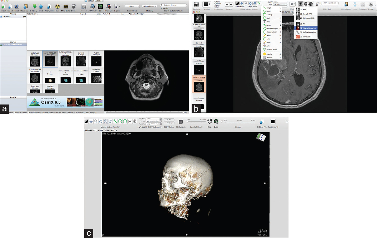
Figure 1
The basic interface of the program. (a) The database section with all the DICOM data; the “Albums section” is the main database with the patient's DICOM files. The “Patient name” menu contains all DICOM patient data, which can be sorted by different categories. Below the “Patient name” section is the window with snapshots of the different radiological sequences. To the right of this window is a small preview of the DICOM images, which are contained in the current selected examination (selected by left clicking on the small snapshot). (b) The 2D viewer is the main window for reviewing the 2D images obtained from the radiological DICOM data. The ROI tools menu (left drop-down menu and its corresponding short keys), as well as the 3D menu (right drop-down menu), is presented. Detailed explanations of image manipulation are given in the text. (c) Snapshot showing the 3D viewer working window. Both the mouse button functions and the clipping mode are discussed in detail in the text. Some of the functions are similar to those of the 2D viewer: WL/WW & CLUT. Other functions, such as control of the details, the function for exporting DICOM images, and FlyThru mode, have short keys on the task bar
Preoperative planning in cranial neurosurgery
Before starting the preoperative planning process, the surgeon must become familiar with both the interface of the program and the image manipulation tools in the 2D and 3D viewer. We use the MRI slices 3-D T1 turbo fast echo and a 1-mm-thick slice, with and without contrast enhancement (for intraaxial lesions and meningiomas), as well as a 1-mm CT thin-cut bone scan and CT angiography (for intracranial aneurysms and meningiomas). These different modalities are presented in detail subsequently.
Planning a case of intra-axial lesion surgery (primary brain tumor, metastasis, brain abscess)
For primary brain tumor cases, the MRI T1 with or without a gadolinium-enhanced sequence is highly useful in presenting the brain–tumor interference in detail, getting an anatomical-like 3D reconstruction of the brain (with and without vessels), and simulating a craniotomy window. The first three steps listed next are to be followed in the 2D viewer.
Estimation of lesion volume [ Video 1h ]
The volume of the lesion is calculated as follows:
In the 2D viewer, the “open polygon” (hotkey “O”) or “closed polygon” (hotkey “C”) tool is selected from the “mouse button function/ROI” tool. The ROI is then carefully marked on several (but not all) axial slices as a way of selecting slices from the most caudal to the most cranial part of the lesion. The next step is to select the “ROI/ROI volume/Generate missing ROIs,” which generates ROIs from the slices that were not included in the selection. Then the “ROI/ROI volume/Compute volume” tool is used to calculate the volume of the lesion by summing the volumes of all the ROIs of all of the slices, both selected and generated. Upon completion of all the calculations, a window pops up with a 3D reconstruction of the lesion and its estimated volume. Later, this 3D ROI can be imported into the 3D viewer by clicking “ROI/ROI manager” and selecting the 3D ROI. This 3D volumetric representation gives a very good idea of the localization of the lesion.
Location of the tumor on the cranium and planning of the craniotomy [ Video 2 ]
The borders of the tumor and the size of the craniotomy can be evaluated by measuring the location of the tumor from the following known anatomical landmarks:
Midline glabella Frontozygomatic suture Root of the zygoma External ear canal Pinna of the ear Posterior part of the petrous bone, just behind the external ear canal Inion Bregma.
The surgeon can estimate the position of the tumor by selecting the “open polygon” (hotkey “O”) tool from the “mouse button function/ROI” tool and measuring in the three planes (coronal, sagittal, axial) from the aforementioned anatomical points. A different-colored ROI point (hotkey “P”) can be placed in each of these points. Together, the ROI points indicate the location of the tumor [
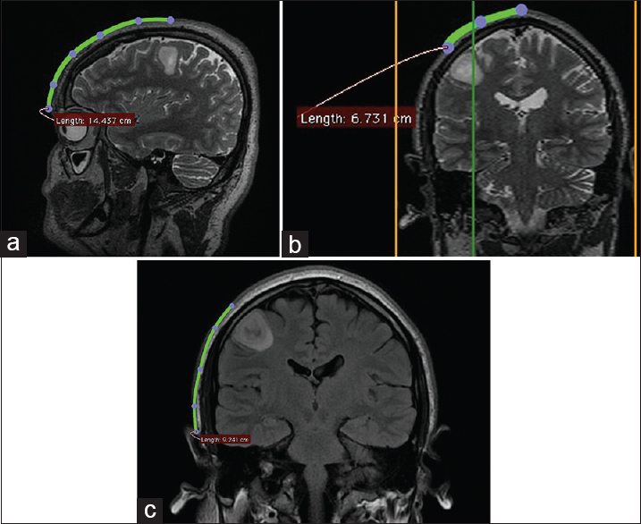
Figure 2
Patient with right frontal low-grade glioma. Location of the lesion, ascertained from measurements from the midpupillary line (a), the midline glabella (b), and the root of the zygoma (c). In measuring distances over the cranium, it is important to use the “open polygon” tool, not the “line” tool, because the cranium is a curved surface and a straight line can give misleading measurements
Marking the projection of the lesion by points on the surface of the cranium [ Video 3 ]
By placing an ROI point (hotkey “P”) in the 2D viewer on the surface of the skin in the axial section, the surgeon can project the borders of the tumor onto the skin and mark these borders. The same maneuver can be repeated for deeper structures to project them onto the surface of the dura/brain cortex and plan a trans-sulcus approach [
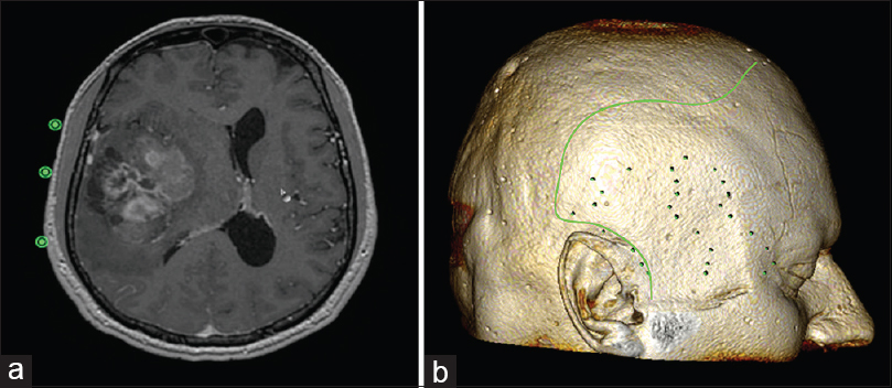
Figure 3
(a) By placing an ROI point (hotkey “P”) in the 2D viewer on the surface of the skin in the axial section, the surgeon can project and mark the borders of the tumor over the surface of the cranium. (b) Then, the surgeon can outline the borders of the tumor in the 2D viewer by selecting the “open polygon” tool after the 3D reconstruction images are exported from the 3D viewer. (For details, see
3D viewer steps
Once the preceding steps are completed, the surgeon enters the 3D viewer mode by selecting the 3D volumetric rendering icon (or “3D viewer/3D volumetric rendering”).
The borders of the tumor are clearly presented in the 3D reconstruction of the patient's head [
There are three options for properly exposing the tumor and simulating the craniotomy window [
Using “Crop” with the cropping cube by reducing the wall (by clicking on the green dot) of the cube and inclining the angles of the cube to expose the tumor. This technique is fast and useful with superficial tumors (metastases and primary brain tumors, abscesses). However, if it is used to reach much deeper lesions, then the section produced in the 3D model by reducing the wall of the cube continues with the whole of its length and distorts much of the image. (It looks like an anatomical section; see Using the “Clipping mode” (with the cursor set to “thick”), by means of which the surgeon can, if desired, represent only the corridor to the lesion, and thereby gain a much better understanding of the lesion itself. With this option, the surgeon selectively eliminates the surrounding tissues. (See “Image manipulation in clipping mode” in Selectively removing the whole skin and cranium, thereby exposing the entire brain surface [
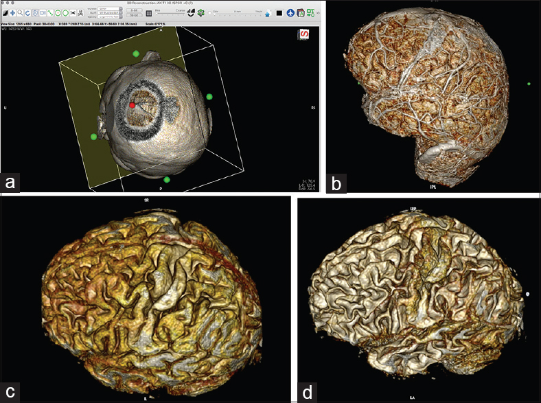
Figure 4
(a) Simulation of the craniotomy window in the 3D viewer with the cropping cube. By clicking on the green dot on the wall of the cube and by gradually reducing the size of the wall, the surgeon can simulate a craniotomy window into a superficial brain lesion. (For details, see
It is important to take selected DICOM image views throughout the entire process. The images obtained can later be exported as JPEG/MOV files or even uploaded to the local hospital server so that they will be accessible in the operation theater.
Fly Thru mode
Fly-through mode can be used to create a detailed video that presents the whole 3D scene and working process in the 3D viewer. The process is initiated simply by selecting fly-through points in the “FlyThru” window; later, the scene is exported as a MOV file.
Exporting the DICOM images after selective removal of skin and bone
After the process of selective removal of skin and bone is completed, one can export the DICOM files of the processed 3D model into the 2D viewer by selecting “File/Export to DICOM files…” followed by “All images of the series including….” Exporting the files will allow the already created 3D model to be used further, without repeating the skin-and-bone removal steps.
Simulating the surgical position, simulating and outlining the skin incision and craniotomy, and measuring point-to-point distances on the 3D model in the 2D viewer
After the desired DICOM images have been created, the 3D window is closed and, in the 2D viewer, the surgeon can simulate the skin incision and tailor the size of the craniotomy on the 3D reconstructed images [Videos
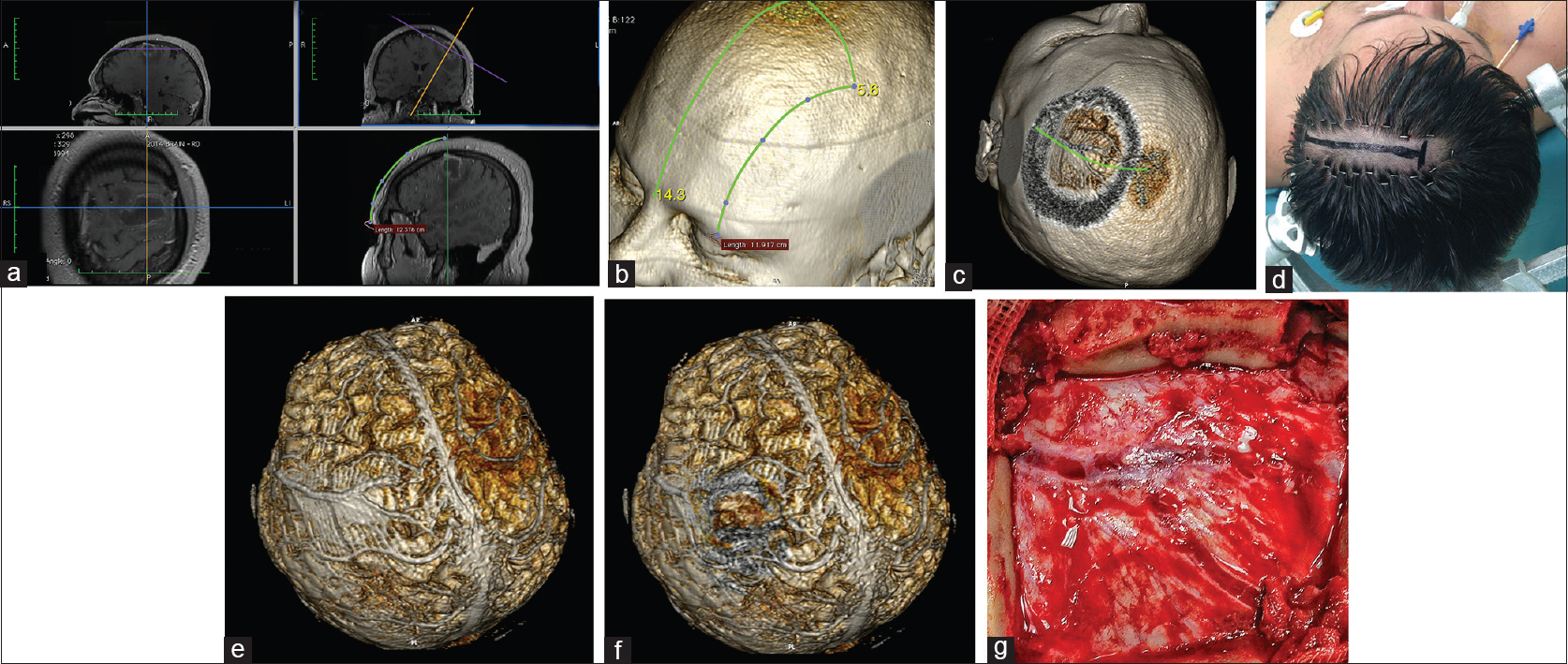
Figure 5
Patient with a brain abscess in the left middle frontal gyrus. (a) Location of the lesion as measured from the middle of the orbital rim. (b) Location of the lesion over the 3D model. (c) Simulation of the craniotomy window, skin incision, and superficial brain anatomy. (d) Minimal hair removal and a linear skin incision centered over the estimated position of the lesion. (e and f) The whole brain after skin-and-bone removal. The abscess is located below the Y-shaped dural venous channels. (g) Intraoperative correlation presenting the Y-shaped dural venous channels in the center of the craniotomy. The abscess was removed with full recovery of the patient
The 3D reconstructions in the DICOM viewer allow for more precise measurement of point-to-point distances on a curved surface (e.g., the patient's skull) with the use of the “open polygon” (hotkey “O”) ROI tool. This tool is more precise than the “line” ROI tool in the 3D viewer and overcomes the difficulties described by other authors in delineating precisely the location of the tumor.[
Planning a case of meningioma surgery (supratentorial, skull base)
For a case of supratentorial meningioma, a contrast-enhanced T1 MRI, MRI angiography, and CT angiography give very useful information regarding the tumor–brain interface, the invasion of vessels (the major brain sinuses) by the tumor, encasement or displacement of cerebral arteries, and bone invasion or hyperostosis [Figures
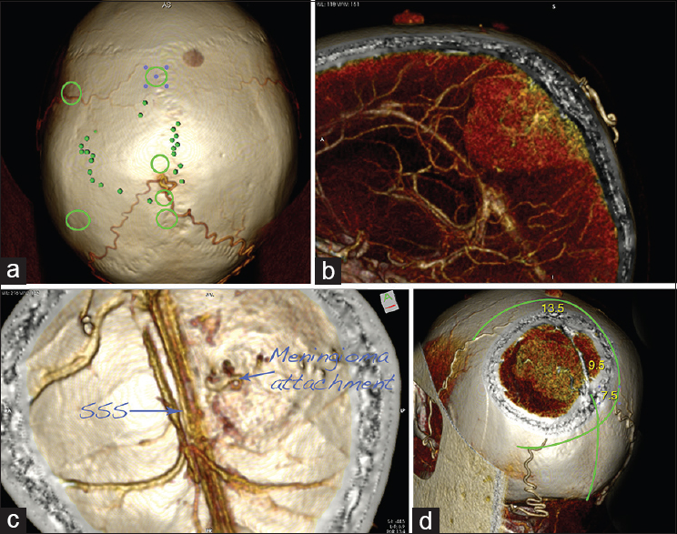
Figure 6
Planning of a case of supratentorial parasagittal meningioma surgery: CT angiography–based 3D reconstructions. (a) The projection of the tumor over the cranium is marked with the small green dots. Note that the tumor is fed by the two occipital arteries, joining together. The green circles mark the location of the burr holes. (b) Sagittal slide presenting the tumor and its major feeding from the occipital arteries. (c) The calvarium is seen from inside. Note the origin of the tumor and the patent superior sagittal sinus (SSS). (d) Planning of the skin incision and craniotomy. The numbers give the beginning of the tumor (7.5 cm), the location of the blood supply (9.5 cm), and the end of the tumor (13.5 cm), measured from the inion
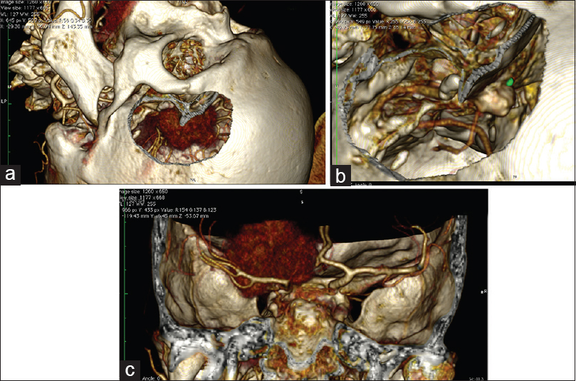
Figure 7
Planning a simulation of a craniotomy of the left anterior clinoid meningioma with the use of CT angiography DICOM data. (For details, see
2D viewer steps
The same principles as described for primary intra-axial lesions in the 2D viewer are employed. The surgeon uses 3D points to outline the surface of the tumor over the cranium and to measure the size and volume of the lesion. Then, the surgeon measures the boundaries of the craniotomy from known anatomical landmarks. After this step is completed the data are loaded into the 3D viewer.
3D viewer steps
Once the marked data from the T1 MRI sequence are loaded into the 3D viewer, one can observe, in 3D, the projection of the tumor over the skin surface of the 3D model. At this point, the desired view is exported as a DICOM file (”File/Export/Export to DICOM file(s)…”), either as a single image or as an animated 360-degree series.
In preoperative planning for meningioma surgery, the surgeon can use the “Clipping mode” in the 3D viewer (with the cursor set to “thick” for full thickness; for details, see second bulleted item in “3D viewer steps” in “Planning a case of intra-axial lesion surgery” section) to rotate the tumor from every possible angle to evaluate the correct brain–tumor interface, as well as to present in detail the encasement of major vessels (as occurs in sphenoid wing meningiomas and anterior clinoid meningiomas) [
Another important consideration in preoperative planning for meningioma surgery is the use of MR angiography, which is good for visualization of the tumor and the associated vessels (as well as, on some occasions, those vessels feeding the tumor) from every possible angle. The view of the image in “Clipping mode” can give important information about the tumor-feeding vessels and whether there is any encasement or displacement of cerebral arteries or invasion of cerebral venous sinuses.
CT angiography and CT bone window in preoperative planning of meningioma surgery
In our experience, one of the most informative examinations for 3D planning in meningioma surgery is preoperative CT angiography [Figures
CTA is also the perfect 3D reconstruction mode to create a simulation of the surgical approach. To tailor a craniotomy in OsiriX software using a thin-cut CT scan, one has to use the different modes of the “Sculpt” tool (see earlier):
The “backspace” key cuts inside the outlined area The “return” key cuts outside the outlined area The “tab” key reconstructs the pixels inside the outlined area.
One of the main features when an approach has to be tailored is that using the “Sculpt” tool with the backspace key to remove the bone also removes all the pixels inside the outlined area. Therefore, the pixels inside the cranium that were cut must be reconstructed (by using the “Sculpt” tool along with the “tab key”) to simulate just a craniotomy window and to visualize the content in the cranium [
Planning the reconstruction after major meningioma surgery
Another important consideration in utilizing the thin-cut CT bone is that the data can be used to plan the reconstruction steps of the surgery: the size of the bone defect after drilling of the hyperostosis, the size of the anterior fossa skull base defect, and the size and length of the pericranial flap.
The size of the bone defect in the three different directions (coronal, axial, sagittal) can be measured in the 2D viewer with the use of the “open polygon” (hotkey “O”) ROI tool. The total area of the hyperostosis can be seen in the 3D viewer as a volumetric reconstruction. In the 3D viewer, the surgeon can tailor a virtual craniotomy by utilizing the “Sculpt” key and exporting the images to the 2D viewer as DICOM files. In this manner, the craniotomy and bone defect can be directly visualized in 3D and precisely simulated, giving a much more detailed visualization. In the 2D viewer, the area of the bone defect can be measured by the “closed polygon” (hotkey “C”) ROI tool. Later, the modified images can be exported into the 2D viewer as a series of separate DICOM files. This method for 3D virtual resectioning and measuring of the bone defect might be faster than the one described by Bruneau et al.[
Planning the size of the pericranial flap used for closure of the dural defect, frontal sinus, and frontal skull base defect is an important step in the reconstruction of the anterior skull base. The “open polygon” (hotkey “O”) ROI tool can be used to plan the size and length of the flap in the 2D viewer; the same tool can be used as well on the previously exported 3D reconstructions in the 2D viewer. The technique is described by Patel et al.[
All the techniques presented yield a precise preoperative understanding of the pathological anatomy, as well as of the relation of the tumor to the normal anatomy, and aid in both the resection itself and the planning of the reconstruction steps.
Preoperative planning in aneurysm surgery
In recent years, OsiriX software has received more and more applications in vascular neurosurgery.[
With CTA, a craniotomy can be simulated in the same manner as described for the meningioma reconstructions. Analogous steps are followed for tailoring the bone window craniotomy and simulating the surgical approach as well as the trajectory to the aneurysm [
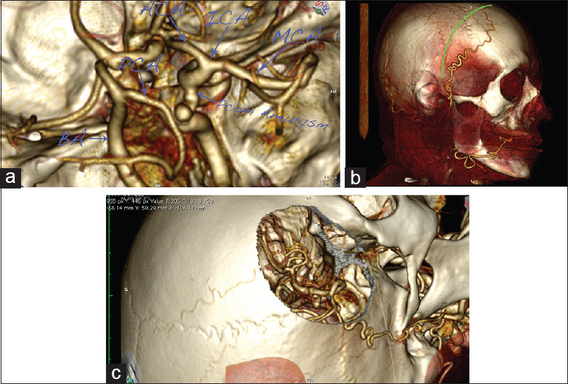
Figure 8
A case of right posterior communicating artery (PCOM) aneurysm. (a) 3D reconstruction of the circle of Willis, presenting an aneurysm on the internal carotid artery (ICA)–PCOM bifurcation. (b) Planned skin incision. Note the major frontal branch of the superficial temporal artery (STA), which is visualized and spared. (c) Virtual pterional craniotomy, presenting the aneurysm
CONCLUSION
OsiriX is a highly efficient program for preoperative preparation and simulation in neurosurgery. It allows DICOM visualization in 2D with comprehensive annotation tools, as well as offering state-of-the-art 3D multiplanar reconstruction, surface-rendering, and volume-rendering possibilities. With its user-friendly interface, the program can be very useful in the hands of residents with sufficient training who are willing to translate their knowledge of anatomy and the data from 2D radiological images to patient-specific 3D reconstructions. The resulting detailed preoperative understanding of the nature of the lesion, as well as the surgical view obtained from simulation of the perspective of intraoperative positioning, will enable the surgeon to achieve better outcomes from the surgery itself.
Financial support and sponsorship
Nil.
Conflicts of interest
There are no conflicts of interest.
Videos Available on: www.surgicalneurologyint.com
References
1. Beyer J, Hadwiger M, Wolfsberger S, Buhler K. High-quality multimodal volume rendering for preoperative planning of neurosurgical interventions. IEEE Trans Vis Comput Graph. 2007. 13: 1696-703
2. Bruneau M, Kamouni R, Schoovaerts F, Pouleau HB, De Witte O. Simultaneous Image-Guided Skull Bone Tumor Resection and Reconstruction With a Preconstructed Prosthesis Based on an OsiriX Virtual Resection. Oper Neurosurg. 2015. 11: 484-90
3. Campero A, Ajler P, Emmerich J, Goldschmidt E, Martins C, Rhoton A. Brain sulci and gyri: A practical anatomical review. J Clin Neurosci. 2014. 21: 2219-25
4. de Notaris M, Palma K, Serra L, Ensenat J, Alobid I, Poblete J. A three-dimensional computer-based perspective of the skull base. World Neurosurg. 2014. 82: S41-8
5. de Notaris M, Topczewski T, de Angelis M, Ensenat J, Alobid I, Gondolbleu AM. Anatomic skull base education using advanced neuroimaging techniques. World Neurosurg. 2013. 79: S16.e19-13
6. Esposito V, Paolini S, Morace R. Resection of a left insular cavernoma aided by a simple navigational tool. Technical note. Neurosurg Focus. 2006. 21: e16-
7. Esposito V, Paolini S, Morace R, Colonnese C, Venditti E, Calistri V. Intraoperative localization of subcortical brain lesions. Acta Neurochir. 2008. 150: 537-42
8. Ferroli P, Tringali G, Acerbi F, Schiariti M, Broggi M, Aquino D. Advanced 3-dimensional planning in neurosurgery. Neurosurgery. 2013. 72: 54-62
9. Harput MV, Gonzalez-Lopez P, Ture U. Three-dimensional Reconstruction of the Topographical Cerebral Surface Anatomy for Pre-surgical Planning With Free OsiriX Software. Oper Neurosurg. 2014. 10: 426-35
10. Jaimovich SG, Guevara M, Pampin S, Jaimovich R, Gardella JL. Neurosurgical planning using osirix software. Surg Neurol Int. 2014. 5: S267-71
11. Jalbert F, Paoli JR. Osirix: Free and open-source software for medical imagery. Rev Stomatol Chir Maxillofac. 2008. 109: 53-5
12. Kuruoglu E, Aydin K, Marangoz A, Cokluk C. The Contribution of Three-Dimensional Computerized Tomographic Angiography in the Head Positioning of the Patients with Middle Cerebral Artery Aneurysms. Turk Neurosurg. 2015. 25: 793-5
13. Mandel M, Amorim R, Paiva W, Prudente M, Teixeira MJ, Andrade AF. 3D preoperative planning in the ER with OsiriX(R): When there is no time for neuronavigation. Sensors (Basel, Switzerland). 2013. 13: 6477-91
14. Mert A, Buehler K, Sutherland GR, Tomanek B, Widhalm G, Kasprian G. Brain tumor surgery with 3-dimensional surface navigation. Neurosurgery. 2012. 71: ons286-94
15. Yasargil MG.editorsMicroneurosurgery. Stuttgart: Thieme; 1994. IVA:
16. Nakajima S, Atsumi H, Kikinis R, Moriarty TM, Metcalf DC, Jolesz FA. Use of cortical surface vessel registration for image-guided neurosurgery. Neurosurgery. 1997. 40: 1201-8
17. Oishi M, Fukuda M, Ishida G, Saito A, Hiraishi T, Fujii Y. Presurgical simulation with advanced 3-dimensional multifusion volumetric imaging in patients with skull base tumors. Neurosurgery. 2011. 68: 188-99
18. Ono M KS, Abernathey CD.editorsAtlas of the Cerebral Sulci. Stuttgart: George Thieme; 1990. p.
19. Patel MR, Shah RN, Snyderman CH, Carrau RL, Germanwala AV, Kassam AB. Pericranial flap for endoscopic anterior skull-base reconstruction: Clinical outcomes and radioanatomic analysis of preoperative planning. Neurosurgery. 2010. 66: 506-12
20. Perhac J, Spaltenstein J, Pereira VM, Schaller K, Brina O, Cabrilo I. Improving workflows of neuro-interventional procedures with autostereoscopic 3D visualization of multi-modality imaging in hybrid interventional suites. Int J Comput Assist Radiol Surg. 2016. 11: 189-96
21. Ribas GC. The cerebral sulci and gyri. Neurosurg Focus. 2010. 28: E2-
22. Rosset A, Spadola L, Ratib O. OsiriX: An open-source software for navigating in multidimensional DICOM images. J Digit Imaging. 2004. 17: 205-16
23. Rotariu D, Budu A, Faiyad Z, Poeata I. The role of OsiriX based virtual endoscopy in planning endoscopic transsphenoidal surgery for pituitary adenoma. Turk Neurosurg. 2017. p. 23-
24. Wang YC, Liu YC, Hsieh TC, Lee ST, Li ML. Aneurysmal subarachnoid hemorrhage diagnosis with computed tomographic angiography and OsiriX. Acta Neurochir. 2010. 152: 263-9
25. Westermaier T, Linsenmann T, Homola GA, Loehr M, Stetter C, Willner N. 3D rotational fluoroscopy for intraoperative clip control in patients with intracranial aneurysms-assessment of feasibility and image quality. BMC Med Imaging. 2016. 16: 30-
26. Westermaier T, Willner N, Vince GH, Linsenmann T, Ernestus RI, Stetter C. Intraoperative 3D rotational angiography: An emergency tool for the diagnosis of intracranial aneurysms. Emerg Radiology. 2015. 22: 97-100
27. Zele T, Matos B, Knific J, Bajrovic FF, Prestor B. Use of 3D visualisation of medical images for planning and intraoperative localisation of superficial brain tumours: Our experience. Br J Neurosurg. 2010. 24: 555-560