- Department of Surgery, Division of Neurosurgery, University of Arizona Medical Center, 1501 N. Campbell Ave. Tucson, Arizona, 85724, USA
Correspondence Address:
Ali A. Baaj
Department of Surgery, Division of Neurosurgery, University of Arizona Medical Center, 1501 N. Campbell Ave. Tucson, Arizona, 85724, USA
DOI:10.4103/2152-7806.156611
Copyright: © 2015 Sattarov K. This is an open-access article distributed under the terms of the Creative Commons Attribution License, which permits unrestricted use, distribution, and reproduction in any medium, provided the original author and source are credited.How to cite this article: Sattarov K, Skoch J, Abbasifard S, Patel AS, Avila MJ, Walter CM, Baaj AA. Posterior atlantoaxial fixation: A cadaveric and fluoroscopic step-by-step technical guide. Surg Neurol Int 07-May-2015;6:
How to cite this URL: Sattarov K, Skoch J, Abbasifard S, Patel AS, Avila MJ, Walter CM, Baaj AA. Posterior atlantoaxial fixation: A cadaveric and fluoroscopic step-by-step technical guide. Surg Neurol Int 07-May-2015;6:. Available from: http://surgicalneurologyint.com/surgicalint_articles/posterior-atlantoaxial-fixation-cadaveric-fluoroscopic/
Abstract
Background:Atlantoaxial surgical fixation is widely employed treatment strategy for a myriad of pathologies affecting the stability of the atlantoaxial joint. The most common technique used in adults, and in certain cases in children, involves a posterior construct with C1 lateral mass screws, and C2 pars or pedicle screws. This technical note aims to provide a step-by-step guide to this procedure using cadaveric and fluoroscopic images.
Methods:An embalmed, human, cadaveric, specimen was used for this study. The subject did not have obvious occipital-cervical pathology. Dissections and techniques were performed to mimic actual surgical technique. Photographs were taken during each step, and the critical aspects of each step were highlighted. Fluoroscopic images from a real patient undergoing C1/C2 fixation were also utilized to further highlight the anatomic-radiographic relationships. This study was performed without external or industry funding.
Results:Photographic and radiographic pictures and drawings are presented to illustrate the pertinent anatomy and technical aspects of this technique. The nuances of each step, including complication avoidance strategies are also highlighted.
Conclusions:Given the widespread utilization of this technique, described step-by-step guide is timely for surgeons and trainees alike.
Keywords: Atlantoaxial fixation, C1 lateral mass, C2 pedicle, C2 pars, goel, harms
INTRODUCTION
Atlantoaxial fixation is an effective treatment modality for instability caused by trauma, rheumatoid arthritis, congenital anomalies, and a myriad of other pathologies.[
Description of the technique
Step 1 – Midline exposure [Figure 1a and b ]
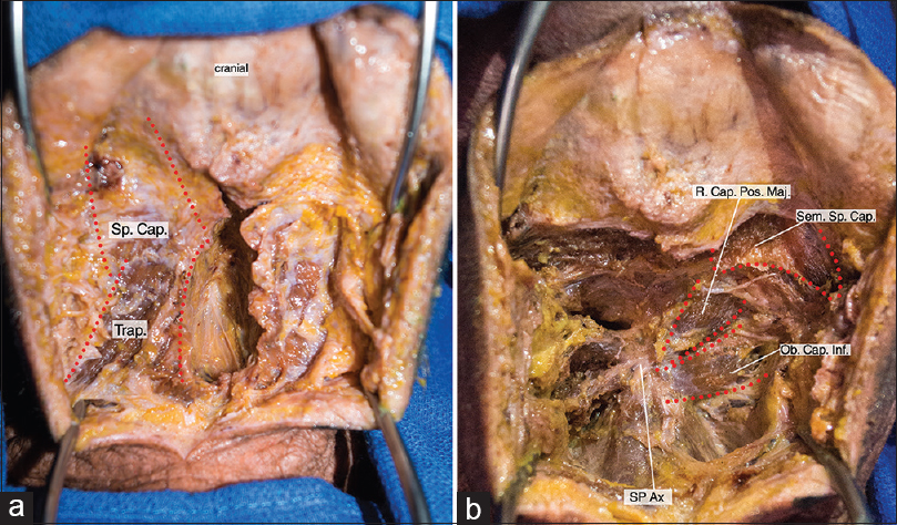
Figure 1
(a) Midline approach to C1/C2. Superior Splenius Capitis is identified and retracted. Sp. Cap: Splenius Capitis muscleTrap: Trapezius muscle (b) Midline Deep incision: Identification of the deep suboccipital muscles. R. Cap. Pos. Maj: Rectus Capitis Posterior Major Sem. Sp. Cap: Semispinalis Capitis muscle Ob.Cap.Inf: Obliquus Capitis Inferior SP Ax: Spinous process of axis
After confirmation of positioning, and after an intraoperative lateral X-ray is obtained to ensure normal atlantoaxial alignment, a midline incision is made from just below the inion to the mid-cervical area. The midline avascular plane is identified, and a retractor is placed between the splenius capitus muscles. Some of the deep suboccipital muscles are then identified, including the inferior rectus oblique, and the rectus capitus major and minor. In exposing the bony landmarks of C1 and C2, the inferior rectus oblique is often dissected off the C2 spinous process. Special care is taken to preserve the subaxial musculature that is attached to the C2 spinous process.
Step 2 – Identification of bony landmarks [ Figure 2 ]
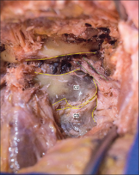
After muscle dissection, the posterior arch of C1 and the lamina of C2 are visualized. Preoperative imaging should be examined carefully to ensure that congenital anomalies are appreciated (e.g., incomplete C1 arch closure). A venous plexus and the C2 nerve root obscure visualization of the C1 lateral mass at this point. However, the C2/3 joint (which should not be violated unless that joint is to be fused), C2 lamina, pars, and pedicle should be exposed and visualized. A number 1 Penfield or similar instrument can be used to glide along the medial pedicle of C2 without puncturing the thecal sac.
Step 3 – Identifying the C1 lateral mass entry point [ Figure 3 ]
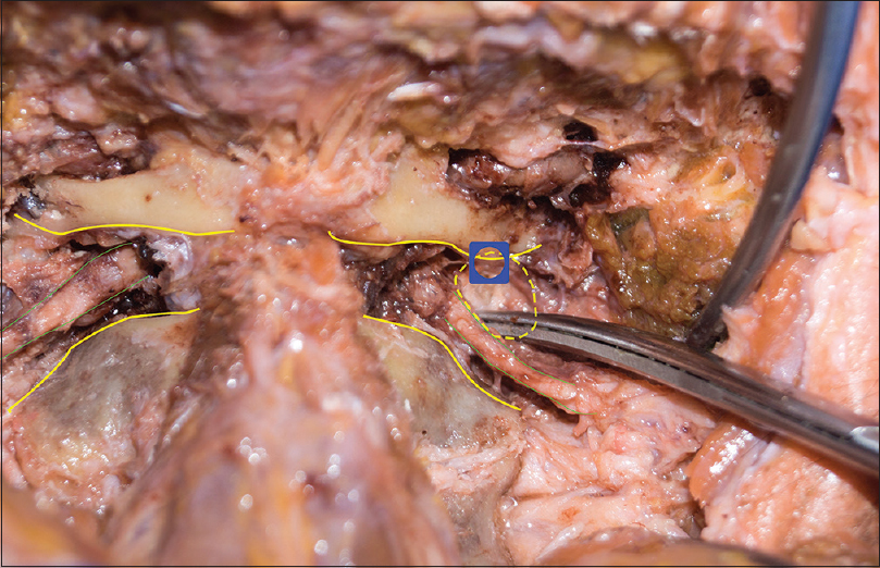
The C1 lateral mass is obscured by a rich venous plexus surrounding the C2 nerve root as it exits the canal. Typically, only the medial and central parts of the C1 lateral mass need exposure, as the vertebral artery lies in close proximity to the lateral edge. The venous plexus is managed by bipolar cautery and hemostatic agents. The C2 nerve root is either retracted caudally, or clipped, and cut. The sequelae of preserving or cutting the C2 nerve root during atlantoaxial fixation is beyond the scope of this technical paper. At this point, the C1 lateral mass, and the C1/2 joint are clearly visualized.
Step 4 – Placing the C1 lateral mass screw [Figure 4a – d ]
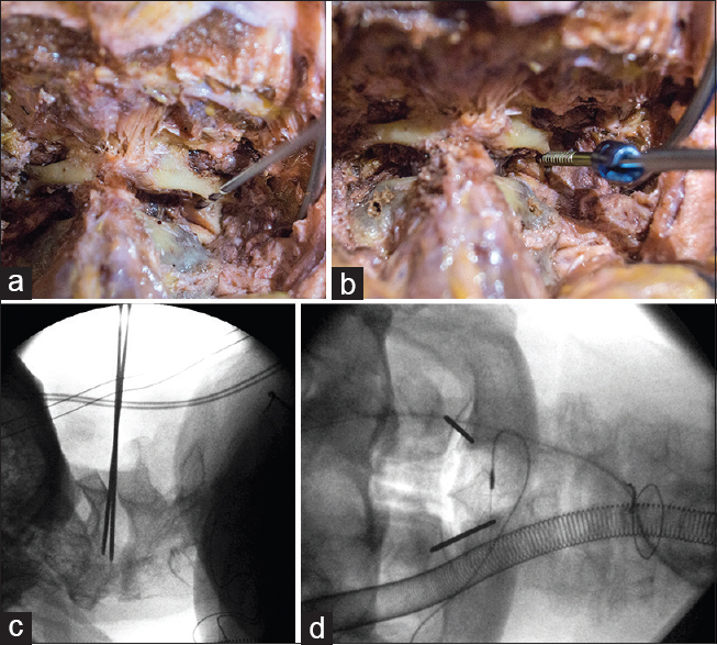
If the C1 lateral mass is robust in size, an entry point can be made directly. Otherwise, the posterior inferior aspect of the arch just above the C1 lateral mass can carefully be undermined with the use of an electric drill. The sulcus arteriosus, upon which the vertebral artery rests, is just superior to this, and thus, only minimal drilling is possible. The medial aspect of the lateral mass is palpated by an instrument, such as a number 4 Penfield or the tip of the drill, and 3–4 mm lateral to this, an entry point is made. This is typically close to the mid-lateral mass posteriorly. The entry point can be made by an awl or matchstick drill bit.
With either an electric or manual drill, or with only a sharp tap, the lateral mass is cannulated in a rostral – medial trajectory (approximately 20 degrees rostral/medial). This can be done free hand or under fluoroscopic guidance. If performed fluoroscopically, the desired trajectory should lead to the posterior aspect of the anterior C1 arch. Diameters and lengths can be measured from the preoperative computed tomography (CT) scan. A screw is placed to match the cannulated trajectory. It is common to place partially threaded screws at C1 so that only the smooth shaft of the screw abuts the C2 nerve root. Typical screw length for the C1 lateral mass is 26–32 mm (the proximal 10 mm of which is typically nonthreaded).
Step 5 – Identifying the C2 pedicle or pars entry point [ Figure 5 ]
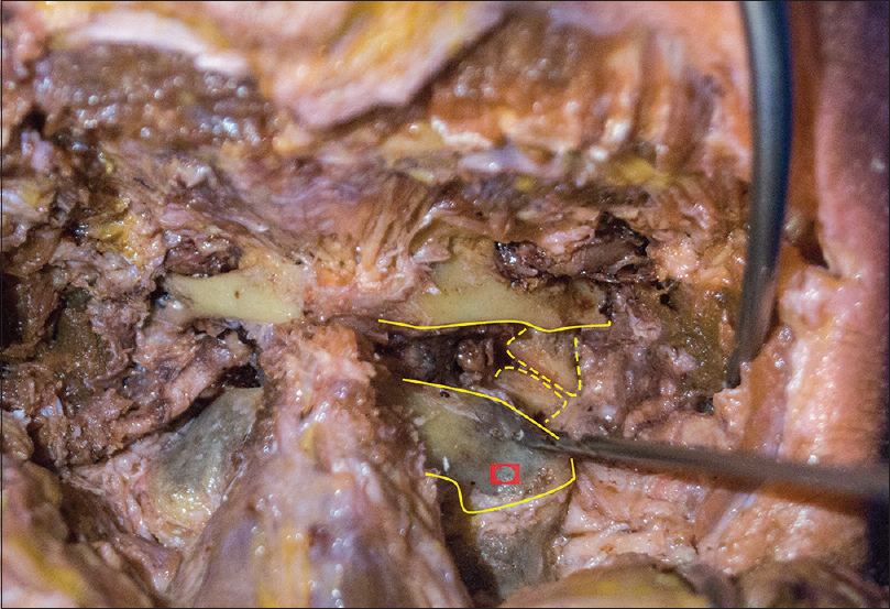
Exposing the pertinent C2 bony anatomy landmarks is critical for safe placement of C2 pars or pedicle screws. The pars entry point is typically a few millimeters rostral to the mid C2/3 facet joint. If only a pars screw is placed, less dissection is necessary up to the medial pedicle/lateral canal of C2. The C2 pedicle entry point is just rostral, and lateral to the C2 pars entry point. The C2 pedicle screw will have a more medial trajectory, and thus, the entry point is more lateral than the pars entry point.
Step 6 – Placing the C2 pars/pedicle screw [Figure 6a – c ]
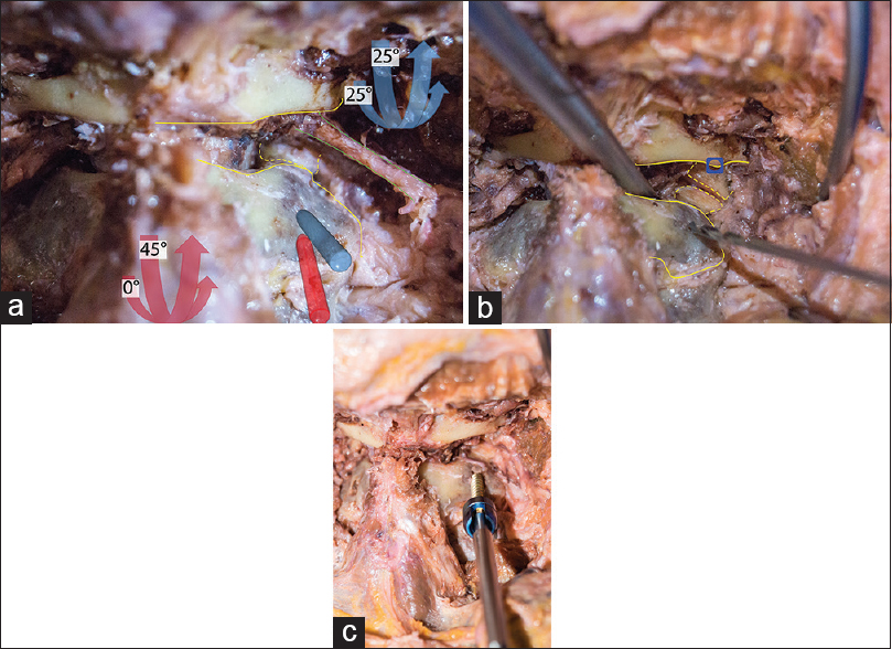
After an entry point is made, the pars or pedicle is cannulated with an electric or manual drill, or alternatively, with a sharp tap. The pars screw trajectory is approximately 0–15 degrees medial, but it has a steep rostral angle (~45 degrees). Typical screw length is 14–18 mm, and care is taken not to breach the vertebral foramen. The pedicle screw has a more medial trajectory, and is not aimed as rostral. Simultaneously visualizing the medial pedicle and advancing the screw, allows for safe medial-lateral trajectory. Typical screw length for the C2 pedicles is 20–28 mm. Longer screws can breach ventrally or more often, superiorly into the C1/C2 joint. A close examination of the preoperative CT is necessary to ensure adequate pedicle size, and normal vertebral artery anatomy.
Step 7 – Completing the fixation construct: [Figure 7a – c ]
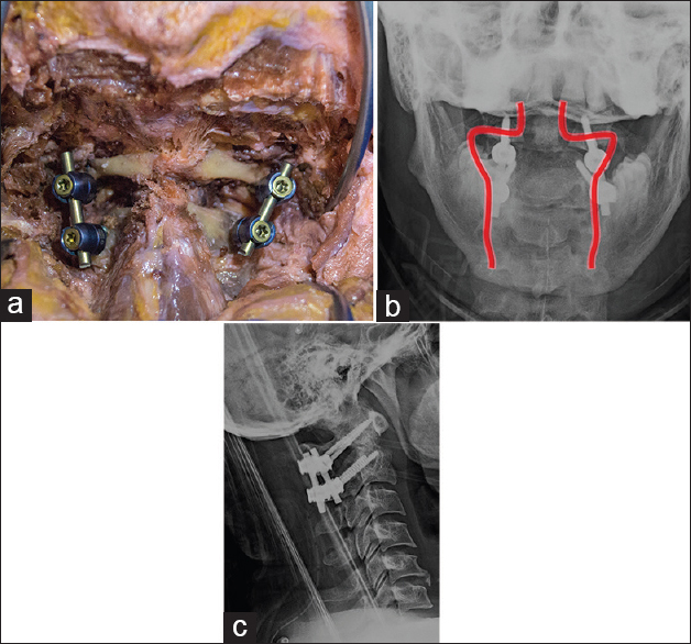
After the C1 and C2 screws are placed, an AP and lateral X-ray are typically taken to ensure all four screws are projecting slightly medial, and that the sagittal trajectories are appropriate. Rods are cut and shaped to match the desired length, and set screws secure the rods to the screw tulips. It is important to appreciate how much reduction is needed (if any), as this affects the offset between C1 and C2 tulips. If good bone purchase is achieved, it is feasible to adequately reduce the atlantoaxial segment as the rods are secured. A crosslink is optional, but is typically not necessary.
Step 8 – Arthrodesis
Achieving arthrodesis is typically a critical goal of atlantoaxial stabilization. After the instrumentation is placed, an electric drill is used to decorticate the posterior C1 arch, the C2 lamina, and the C1/C2 joint space. If a laminectomy was performed, then the lateral aspects of the C1 arch and C2 lamina can still be decorticated. The graft material of choice can be placed over the decorticated surfaces.
Step 9 – Closure
A surgical drain is optional, but if used, it is typically placed subfacially. The wound is closed in several layers and includes the deep muscles, the fascia, the superficial subcutaneous layers, and then the skin. The skin can be closed with surgical staples, absorbable subcuticular, or running nonabsorbable suture.
DISCUSSION
C1 lateral mass and C2 pars/pedicle screw and rod fixation is common and effective[
CONCLUSION
Atlantoaxial fixation is an essential technique in the treatment of various pathologies affecting that segment of the cervical spine. A thorough understanding of the regional anatomy and nuances of the technique is mandatory for safe and effective implementation. This step-by-step, illustrated guide aims to facilitate understanding of one of the most common atlantoaxial fixation strategies, the C1 lateral mass and C2 pars-pedicle screw and rod fixation technique.
References
1. Apuzzo ML, Heiden JS, Weiss MH, Ackerson TT, Harvey JP, Kurze T. Acute fractures of the odontoid process. An analysis of 45 cases. J Neurosurg. 1978. 48: 85-91
2. Brockmeyer DL. Lateral mass screw fixation of C-1. J Neurosurg. 2007. 107: 173-7
3. Coyne TJ, Fehlings MG, Wallace MC, Bernstein M, Tator CH. C1-C2 Posterior Cervical Fusion: Long Term Evaluation of Results and Efficacy. Neurosurg. 1995. 37: 688-93
4. Gallie WE. Fractures and Dislocations of Cervical Spine. Am J Surg. 1939. 46: 495-9
5. Goel A. Treatment of basilar invagination by atlantoaxial joint distraction and direct lateral mass fixation. J Neurosurg Spine. 2004. 1: 281-6
6. Goel A, Desai KI, Muzumdar DP. Atlantoaxial fixation using plate and screw method: A report of 160 treated patients. Neurosurgery. 2002. 51: 1351-6
7. Goel A, Pareikh S, Sharma P. Atlantoaxial joint distraction for treatment of basilar invagination secondary to rheumatoid arthritis. Neurol India. 2005. 53: 238-40
8. Goel A, Phalke U, Cacciola F, Muzumdar D. Atlantoaxial instability and retroodontoid mass-two case reports. Neurol Med Chir (Tokyo). 2004. 44: 603-6
9. Goel A, Karapurkar AP. Transoral plate and screw fixation of the craniovertebral region-a preliminary report. Br J Neurosurg. 1994. 8: 743-5
10. Goel A, Kulkarni AG. Mobile and reducible atlantoaxial dislocation in presence of occipitalized atlas: Report on treatment of eight cases by direct lateral mass plate and screw fixation. Spine. 2004. 29: E520-3
11. Goel A, Kulkarni AG, Sharma P. Reduction of fixed atlantoaxial dislocation in 24 cases: Technical note. J Neurosurg Spine. 2005. 2: 505-9
12. Grob D, Criseo JJ, Panjabi MM, Wang P, Dvorak J. Biomechanical evaluation of four different posterior atlantoaxial fixation techniques. Spine. 1992. 17: 480-90
13. Grob D, Magerl F. Surgical stabilization of C1 and C2 fractures. Orthopade. 1987. 16: 46-54
14. Gunnarsson T, Massicotte EM, Govender PV, Raja Rampersaud Y, Fehlings MG. The use of C1 lateral mass screws in complex cervical spine surgery: Indications, techniques, and outcome in a prospective consecutive series of 25 cases. J Spinal Disord Tech. 2007. 20: 308-16
15. Harms J, Melcher PP. Posterior C1-C2 fusion with polyaxial screw and rod fixation. Spine. 2001. 26: 2467-71
16. Hadley MN, Browner C, Sonntag VK. Axis fractures: A comprehensive review of management and treatment in 107 cases. Neurosurgery. 1985. 17: 281-90
17. Hertlein H, Mittlmeier T, Schürmann M, Lob G. Posterior stabilization of C2 metastases by combination of atlantoaxial screw fixation and hook plate. Eur Spine J. 1994. 3: 52-5
18. Jeanneret B, Magerl F. Primary Posterior Fusions C1-2 in Odontoid Fractures: Indications, Technique, and Results of Transarticular Screw Fixation. J Spinal Disord. 1992. 5: 464-75
19. Maak TG, Grauer JN. The contemporary treatment of odontoid injuries. Spine (Phila Pa 1976). 2006. 31: S53-60
20. Meijers KA, Van Beusekom JT, Luyendijk W, Duijfjes F. Dislocation of the Cervical Spine with cord Compression Rheumatoid Arthritis. J Bone Joint Surg. 1974. 56-B: 668-80
21. Mixter SJ, Osgood RB. Traumatic Lesions of the Atlas and Axis. Ann Surg. 1910. 51: 193-207
22. Mummaneni PV, Haid RW, Traynelis VC, Sasso RC, Subach BR, Fiore AJ. Posterior cervical fixation using a new polyaxial screw and rod system: Technique and surgical results. Neurosurg Focus. 2002. 12: E8-
23. Mummaneni PV, Haid RW. Atlantoaxial fixation: Overview of all techniques. Neurol India. 2005. 53: 408-15
24. O’Brien JR, Gokaslan ZL, Riley LH, Suk I, Wolinsky JP. Open reduction of C1-C2 subluxation with the use of C1 lateral mass and C2 translaminar screws. Neurosurgery. 2008. 63: ONS95-8