- Department of Neurosurgery, National Institute of Mental Health and Neurosciences (NIMHANS), Bengaluru, Karnataka, India
- Department of Neuroimaging and Interventional Radiology, National Institute of Mental Health and Neurosciences (NIMHANS), Bengaluru, Karnataka, India
- Department of Biostatistics, National Institute of Mental Health and Neurosciences (NIMHANS), Bengaluru, Karnataka, India
- Department of Neurosurgery, All India Institute of Medical Sciences, Raipur, Chhattisgarh, India
- Department of Human Anatomy, St. Johns Medical College, Bengaluru, Karnataka, India
Correspondence Address:
Nupur Pruthi
Department of Biostatistics, National Institute of Mental Health and Neurosciences (NIMHANS), Bengaluru, Karnataka, India
DOI:10.4103/sni.sni_109_18
Copyright: © 2018 Surgical Neurology International This is an open access journal, and articles are distributed under the terms of the Creative Commons Attribution-NonCommercial-ShareAlike 4.0 License, which allows others to remix, tweak, and build upon the work non-commercially, as long as appropriate credit is given and the new creations are licensed under the identical terms.How to cite this article: Nupur Pruthi, Lokesh Nehete, Tanmoy Maity, Rose Dawn, Yogita Ravindranath, Roopa Ravindranath, Mariamma Philips. Can the position of the vertebral artery be predicted on a lateral view X-ray of the craniovertebral junction? A radiological anatomy study. 26-Jun-2018;9:124
How to cite this URL: Nupur Pruthi, Lokesh Nehete, Tanmoy Maity, Rose Dawn, Yogita Ravindranath, Roopa Ravindranath, Mariamma Philips. Can the position of the vertebral artery be predicted on a lateral view X-ray of the craniovertebral junction? A radiological anatomy study. 26-Jun-2018;9:124. Available from: http://surgicalneurologyint.com/surgicalint-articles/can-the-position-of-the-vertebral-artery-be-predicted-on-a-lateral-view-x%e2%80%91ray-of-the-craniovertebral-junction-a-radiological-anatomy-study/
Date of Submission
10-Apr-2018
Date of Acceptance
11-May-2018
Date of Web Publication
26-Jun-2018
Abstract
Background:The most feared complication while inserting C2 screws is vertebral artery injury. This article proposes predicting the position of the vertebral artery on a true lateral X-ray of the axis vertebra from the background information acquired from the computed tomography (CT) scan utilizing fluoroscopy.
Methods:Spiral CT scans of 33 C2 vertebrae were performed utilizing a 16-slice CT scanner lateral X-rays of C2 were then obtained before and after painting the vertebral artery grooves with barium. The space available for transarticular and C2 pedicle screw insertion above the vertebral artery groove in the isthmus was then calculated as a ratio for both X-rays and CT scans.
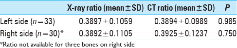
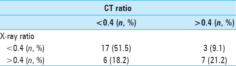
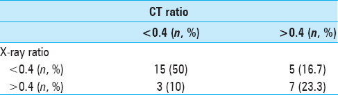
Results:There was no statistically significant difference between the (mean) ratios calculated by CT scan and X-rays regarding the space available for transarticular and C2 pedicle screw insertion (left side: 0.3894 vs 0.3897; right side: 0.3892 vs 0.3925; P > 0.05). The Kappa test revealed that CT scan and X-ray findings were in agreement in majority of the bones (left side: n = 24, 72.7%, right side: n = 22, 73.3%; P
Conclusion:A thorough understanding of a true lateral view X-ray based on background information extracted from three dimensional CT scans helps predict the highest point of the vertebral artery groove. This proves useful for placement of C2 transarticular and pedicle screws during regular “open” and “minimally invasive” spine surgery.
Keywords: C2 pedicle screw, fluoroscopy, transarticular screw, vertebral artery
INTRODUCTION
The most feared complication while inserting C2 screws is vertebral artery injury.[
MATERIAL AND METHODS
Thirty-three adult dry axis bones were obtained from the Department of Human Anatomy. The samples were inspected to ensure that all the axes were free from anomalies and pathological destructions. Spiral CT scans of these dry axis vertebrae were done on a 16-slice scanner (Brilliance Philips). Subsequently, they were subjected to lateral view X-rays in a digital subtraction angiography suite (Siemens).
X-ray protocol
First, a true lateral view [
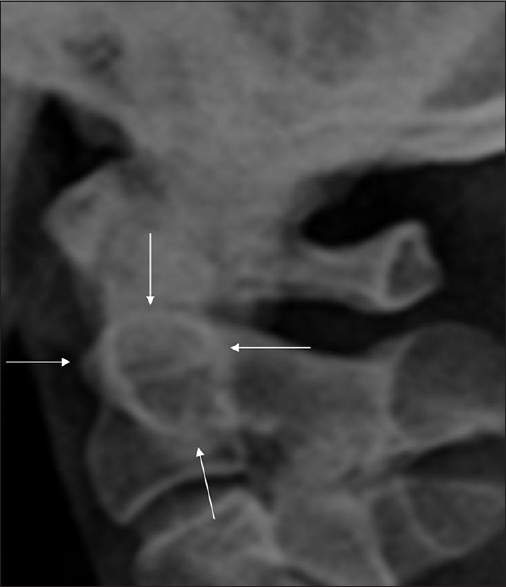
Figure 1
The normal ring of the axis (arrows). The highest point on the superior arc corresponds to the highest point of the superior articulating facets of the axis. The anterior curvilinear arc is composed of the anterior cortex of the axis at the junction of the body and its contiguous lateral structures. The superior arc is a distinct composite shadow consisting of the density produced by the cortex of the obliquely oriented superior articulating facets of the axis superimposed upon the superior cortex of the body between the dens and the superior facets. The posterior, vertical, straight arc is produced by the posterior cortex of the body of the axis. The characteristically discontinuous posteroinferior portion of the ring is caused by the foramen transversarium. The latter occasionally produces a distinct ring
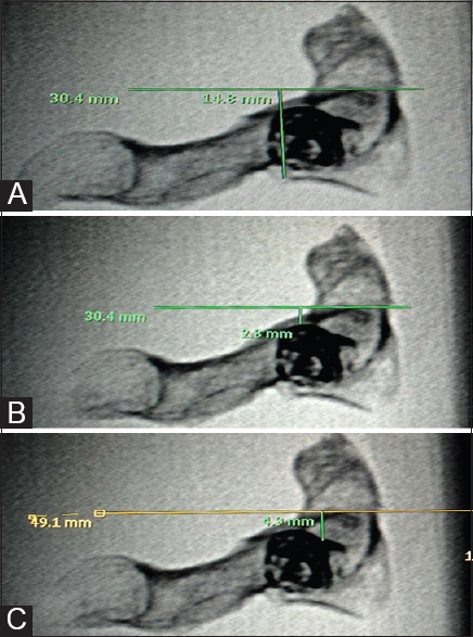
Figure 2
Lateral view X-ray taken after painting both vertebral artery grooves with barium sulfate. (A) Method of measuring common denominator (d): A perpendicular line is dropped from the posterior and inferior corner of the C2 body to a line that passes tangential to the highest point on the superior arc of the “ring of Axis”. (B) A perpendicular is dropped to the same line from the top of left vertebral artery groove (outlined by barium sulfate). This is distance “a.” (C) A perpendicular is dropped to the same line from the top of right vertebral artery groove (outlined by barium sulfate). This is distance “b.” The X-ray ratio for left side is calculated by the formula: a/d; and on the right side by b/d
Computed tomography protocol
Axial images were reconstructed (Brilliance Philips CT work station) parallel to the base of body of axis with a slice thickness of 0.5 mm. The slice that passed through the highest point of both superior facets was selected. On the workstation, the position of this cut on a midsagittal image was noted and the common denominator was measured as shown in Figure
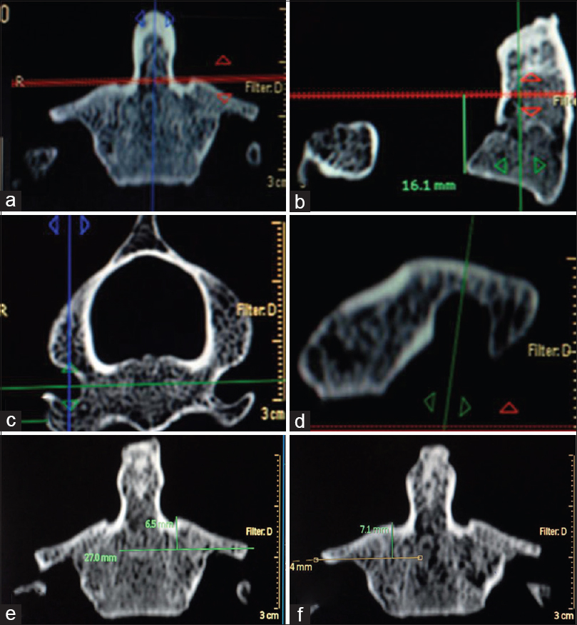
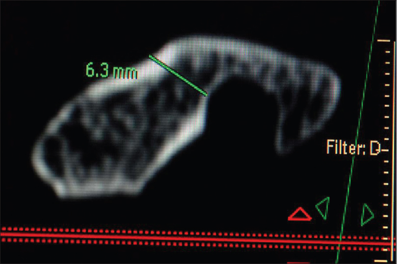
Figure 3
(a) In the coronal image, an axial slice that passes through the highest point of both superior facets is selected. On the workstation, the position of this cut on a midsagittal image (b) is noted and the common denominator is measured (z). (c) Proper coronal images are reconstructed parallel to the posterior border of C2 body as seen in axial slices.(d) A coronal image passing through the highest point of the vertebral artery groove as seen in a parasagittal cut is chosen. (e) In this selected coronal image, a tangent is drawn from the top of the left vertebral artery groove and a perpendicular (x) is dropped on it from the medial most point of the ipsilateral superior articular facet. (f) A tangent is drawn from the top of the right vertebral artery groove and a perpendicular (y) is dropped on it from the medial most point of the ipsilateral superior articular facet. Left side ratio is calculated by the formula: x/z and right side ratio by the formula: y/z
SPSS 15.0 software was used for statistical analysis. The level of significance was fixed at 0.05. Paired t test was used to compare the ratios. Kappa statistics was calculated to find out the agreement between X-ray and CT-based ratios.
RESULTS
There was no statistically significant difference between the ratios calculated by CT scan and X-rays [
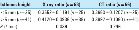
Isthmus height is a universally acceptable CT parameter used to predict difficulty in inserting C1–C2 transarticular screws and C2 pedicle screws.[
The transverse foramen of the axis was seen well on a true lateral view X-ray in the posteroinferior part of the ring in 36.4% (12/33) of the dry bones [
DISCUSSION
In this study, we proposed a new CT parameter in the form of a ratio, which can predict with good accuracy, the position of the highest point of the vertebral artery groove while using intraoperative fluoroscopy (separately for each side). The information can be extremely vital to avoid the feared complication of vertebral artery injury. While inserting a transarticular screw, the screw trajectory has to be superior to the vertebral artery groove. A C2 pedicle screw usually traverses superomedial or just superior to this groove.[
The use of spinal navigation has been shown to improve the accuracy of pedicle screw placement, also in the cervical spine.[
Liu et al.[
This study highlighted the significance of the “Ring of Axis” in inserting transarticular and C2 pedicle screws. We demonstrated that a true lateral view is a simple, reliable, and reproducible method to identify intraoperatively the position of the highest point of the vertebral artery groove at the C2 level based on assessment of 33 dry bones.
CONCLUSION
A thorough understanding of a true lateral view X-ray based on the background information extracted from a three dimensional CT scan can help to predict with good accuracy the highest point of the vertebral artery groove. This information can be very useful for regular and minimally invasive spine surgery in this region.
Financial support and sponsorship
Nil.
Conflicts of interest
There are no conflicts of interest.
References
1. Amiot LP, Lang K, Putzier M, Zippel H, Labelle H. Comparative results between conventional and computer-assisted pedicle screw installation in the thoracic, lumbar, and sacral spine. Spine. 2000. 25: 606-14
2. Finn MA, Apfelbaum RI. Atlantoaxial transarticular screw fixation: Update on technique and outcomes in 269 patients. Neurosurgery. 2010. 66: 184-92
3. Grob D, Jeanneret B, Aebi M, Markwalder TM. Atlanto-axial fusion with transarticular screw fixation. JBone Joint Surg. 1991. 73: 972-6
4. Kotani Y, Abumi K, Ito M, Minami A. Improved accuracy of computer-assisted cervical pedicle screw insertion. JNeurosurg. 2003. 99: 257-63
5. Liu J, Shafiq Q, Ebraheim NA, Karkare N, Asaad M, Woldenberg L. Value of intraoperative true lateral radiograph of C2 pedicle for C1-2 transarticular screw insertion. Spine. 2005. 5: 434-40
6. Madawi AA, Casey AT, Solanki GA, Tuite G, Veres R, Crockard HA. Radiological and anatomical evaluation of the atlantoaxial transarticular screw fixation technique. J Neurosurg. 1997. 86: 961-8
7. Pruthi N, Dawn R, Ravindranath Y, Maiti TK, Ravindranath R, Philip M. Computed tomography-based classification of axis vertebra: choice of screw placement. Eur Spine J. 2014. 23: 1084-91
8. Richter M, Amiot LP, Neller S, Kluger P, Puhl W. Computer-assisted surgery in posterior instrumentation of the cervical spine: an in-vitro feasibility study. Eur Spine J. 2000. 9: S65-70
9. Wright NM, Lauryssen C. Vertebral artery injury in C1-2 transarticular screw fixation: results of a survey of the AANS/CNS section on disorders of the spine and peripheral nerves. American Association of Neurological Surgeons/Congress of Neurological Surgeons. JNeurosurg. 1998. 88: 634-40
10. Yoshida M, Neo M, Fujibayashi S, Nakamura T. Comparison of the anatomical risk for vertebral artery injury associated with the C2-pedicle screw and atlantoaxial transarticular screw. Spine. 2006. 31: E513-7