- Department of Surgery, Faculty of Medicine Vajira Hospital, Navamindradhiraj University, Bangkok, Thailand.
- Department of Health Technology, Faculty of Science and Health Technology, Navamindradhiraj University, Bangkok, Thailand.
Correspondence Address:
Kitiporn Sriamornrattanakul, Department of Surgery, Faculty of Medicine Vajira Hospital, Navamindradhiraj University, Bangkok, Thailand.
DOI:10.25259/SNI_346_2022
Copyright: © 2022 Surgical Neurology International This is an open-access article distributed under the terms of the Creative Commons Attribution-Non Commercial-Share Alike 4.0 License, which allows others to remix, transform, and build upon the work non-commercially, as long as the author is credited and the new creations are licensed under the identical terms.How to cite this article: Kitiporn Sriamornrattanakul1, Nasaeng Akharathammachote1, Areeporn Chonhenchob1, Atithep Mongkolratnan1, Nattawut Niljianskul1, I-Sorn Phoominaonin2, Chanon Ariyaprakai1, Somkiat Wongsuriyanan1. Course of the V3 segment of the vertebral artery relative to the suboccipital triangle as an anatomical marker for a safe far lateral approach: A retrospective clinical study. 15-Jul-2022;13:304
How to cite this URL: Kitiporn Sriamornrattanakul1, Nasaeng Akharathammachote1, Areeporn Chonhenchob1, Atithep Mongkolratnan1, Nattawut Niljianskul1, I-Sorn Phoominaonin2, Chanon Ariyaprakai1, Somkiat Wongsuriyanan1. Course of the V3 segment of the vertebral artery relative to the suboccipital triangle as an anatomical marker for a safe far lateral approach: A retrospective clinical study. 15-Jul-2022;13:304. Available from: https://surgicalneurologyint.com/?post_type=surgicalint_articles&p=11715
Date of Submission
12-Apr-2022
Date of Acceptance
29-Jun-2022
Date of Web Publication
15-Jul-2022
Abstract
Background: The third segment of the vertebral artery (V3) is vulnerable during far lateral and retrosigmoid approaches. Although the suboccipital triangle (SOT) is a useful anatomical landmark, the relationship between V3 and the muscles forming the triangle is not well-described. We aimed to demonstrate the relationship between the V3, surrounding muscles, and SOT in clinical cases.
Methods: Operative videos of patients with the vertebral artery (VA) and posterior inferior cerebellar artery (PICA) aneurysms treated with occipital artery-PICA bypass through the far lateral approach were examined. Videos from January 2015 to October 2021 were retrospectively reviewed to determine anatomy of the V3 and the SOT.
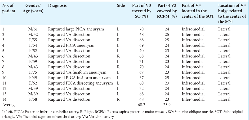
Results: Fourteen patients were included in this study. The ipsilateral V3 was identified without injury in all patients using the bipolar cutting technique. The lateral 68.2% of the horizontal V3 segment, including the V3 bulge, was covered by the inferomedial part of the superior oblique muscle (SO). The medial 23.9% was covered by the inferolateral part of the rectus capitis posterior major muscle. The inferomedial part of the horizontal V3 segment is located within the SOT.
Conclusion: Most of the V3, including the V3 bulge, were located beneath the SO and the inferomedial part of V3 located within the SOT. Elevation of the SO should be performed carefully using the bipolar cutting technique to avoid injury to the V3. To the best of our knowledge, this is the first description of the V3 relative to the SOT in the clinical setting.
Keywords: Far lateral approach, Suboccipital triangle, Superior oblique muscle, V3 segment, Vertebral artery
INTRODUCTION
The suboccipital segment or the third segment of the vertebral artery (VA) (V3) extends from the transverse foramen of C1 to the foramen magnum. This segment of the VA runs horizontally in the groove of the posterior arch of C1 (J-groove or C1 sulcus arteriosus).[
Dorsolateral and far lateral approaches (retrocondylar, transcondylar, and transcondylar fossa variants) are indicated when accessing the lower clivus, anterolateral foramen magnum, VA, or posterior inferior cerebellar artery (PICA). The V3 is usually identified, skeletonized, and preserved while utilizing these approaches.[
MATERIALS AND METHODS
Patient selection
The operative videos of patients with VA and PICA aneurysms and dissections treated by occipital artery-PICA (OA-PICA) bypass through the far lateral approach between January 2015 and October 2021 were retrospectively reviewed. The V3 anatomy relative to the surrounding muscles and SOT was examined.
Operative technique
With the patient in the semi-prone park bench position [
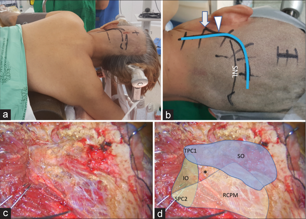
Figure 1:
(a) Semi-prone park bench position. (b) Reverse “L” shape incision relative to the mastoid tip (arrow), mastoid groove (arrowhead), and superior nuchal line (SNL). (c and d) After the sternocleidomastoid, splenius capitis, longissimus capitis, and semispinalis capitis muscles and the posterior belly of digastric muscle were elevated in layers, the transverse process of C1 (TPC1) and the spinous process of C2 (SPC2) were palpated and the suboccipital triangle (asterisk) formed by the superior oblique (SO in blue color), inferior oblique (IO in green color), and rectus capitis posterior major (RCPM in yellow color) muscles was identified.
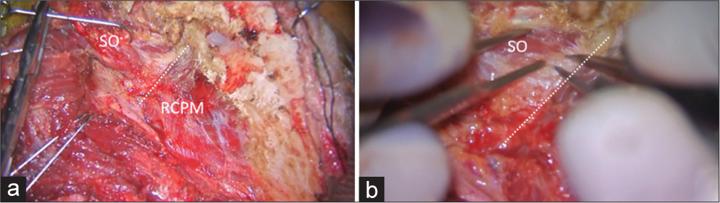
Figure 2:
Intraoperative photograph demonstrating left suboccipital muscle dissection. (a) After inferolateral elevation of the superior oblique muscle (SO) from the rectus capitis posterior major muscle (RCPM), the inferolateral border (dashed line) of the RCPM was identified as the landmark of the third segment of the vertebral artery (V3) and the starting point for the bipolar cutting technique to separate the SO from the V3. (b) Magnified photograph of Panel A demonstrated the inferolateral border (dashed line) of the RCPM and the partially elevated SO.
Video 1
Quantitative measurements
After full exposure of the V3 was completed, the long axis of the V3 was marked [
RESULTS
Patient characteristics
The far lateral transcondylar or transcondylar fossa approaches and OA-PICA bypass was performed in 14 patients with VA and proximal PICA aneurysms and dissections. The ipsilateral V3 was identified in all patients. The average patient age was 54 years. All patients suffered from subarachnoid hemorrhage (SAH) at initial presentation. VA dissections were the most common type of lesion (64.3%), followed by saccular aneurysms of the VA-PICA junction (28.6%). Surgeries were performed on the left side in 10 patients (71.4%) and on the right side in four patients (28.6%) [
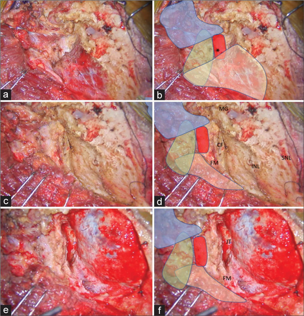
Figure 3:
(a and b) After the SO (in blue color) was inferolaterally elevated, the V3 (red color) was identified beside the RCPM (yellow color) and IO (green color). The location of the center of the suboccipital triangle is marked with an asterisk. (c and d) After the RCPM (yellow color) was inferomedially elevated from the inferior nuchal line, the foramen magnum (FM) was exposed. The condylar fossa (CF), SNL, and mastoid groove (MG) were also identified. (e and f) After retrosigmoid craniotomy, removal of the posterolateral part of the FM, and drilling of the CF, the posterior part of jugular tubercle (JT), and the medial part of the occipital condyle, the transcondylar exposure was completed.
Video 2
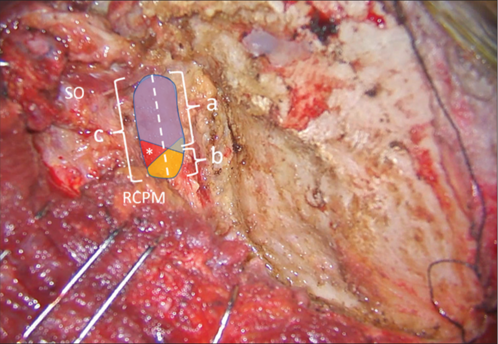
Figure 4:
Method of quantitative measurement of the V3 length on the left side. The superior oblique (SO) and rectus capitis posterior major (RCPM) muscles were identified. The whole length of the V3 was marked as a dashed line and measured as “c.” The length of the V3 covered by SO (blue color) and RCPM (yellow color) were measured as “a” and “b,” respectively. The center of the suboccipital triangle above the V3 is indicated with an asterisk.
Operative findings
After elevation of the SO, the V3 covered by the venous plexus was observed just inferolateral to the inferolateral border of the RCPM. After full elevation of the SO and RCPM, the lateral 60–72% of the V3 was covered by the inferomedial part of the SO. The medial 23–25% of the V3 was covered by the inferolateral part of RCPM. On average, the SO and RCPM covered the lateral 68.2% and medial 23.9% of the V3, respectively [
ILLUSTRATIVE CASES
Case 1 (Patient 1)
A 61-year-old male presented with sudden alteration of consciousness (AOC). The World Federation of Neurosurgical Societies (WFNS) grade was 5 at the presenting hospital. Computed tomography (CT) showed a diffuse SAH. A large and wide neck saccular aneurysm at the first and second segment of the left PICA was detected by computed tomography angiography (CTA). A left far lateral transcondylar approach [
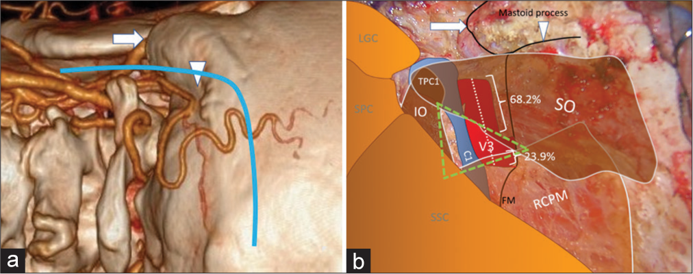
Figure 5:
(a) Three-dimensional reconstructed computed tomography angiography of the left side of the craniocervical junction demonstrating the skin incision (blue line), mastoid tip (arrow), and mastoid groove (arrowhead). (b) An intraoperative photograph, similar to Panel A, demonstrating the mastoid tip (arrow), mastoid groove (arrowhead), the third segment of the vertebral artery (V3 and red color), the suboccipital triangle (green triangle), and the related suboccipital muscles. The lateral 68.2% and medial 23.9% of the V3 are covered by the superior oblique muscle (SO) and rectus capitis posterior major muscle (RCPM), respectively. The inferomedial part of the V3 is located within the suboccipital triangle (green triangle). (C1: Posterior arch of C1, FM: Foramen magnum, IO: Inferior oblique muscle, LGC: Longissimus capitis muscle, RCPM: Rectus capitis posterior major muscle, SO: Superior oblique muscle, SPC: Splenius capitis muscle, SSC: Semispinalis capitis muscle, TPC1: Transverse process of C1).
Case 2 (Patient 13)
A 39-year-old male presented with sudden AOC with an initial WFNS grade of 4. CT showed diffuse SAH predominantly at the premedullary cistern. A left vertebral artery dissection (VAD) with PICA involvement was detected through CTA. A left far lateral transcondylar fossa approach was performed [
Case 3 (Patient 14)
A 58-year-old female presented with sudden AOC. The WFNS grade was 4 at the first hospital. CT showed a diffuse SAH. A right VAD and right PICA originating from the dissecting segment were detected through CTA. OA-PICA bypass and blind-alley formation were performed through a right far lateral transcondylar approach [
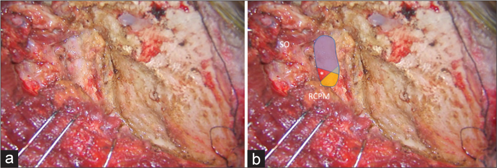
Figure 6:
Illustrative Case 1 (Patient 1) (a and b) Intraoperative finding of the left suboccipital muscle dissection and exposure for the far lateral transcondylar approach. (b) The superior oblique (SO) and rectus capitis posterior major muscle (RCPM) were elevated. The third segment of the vertebral artery (blue, red, and yellow colors) was exposed. The blue color was covered by the SO, which included the lateral 70% of the third segment of the vertebral artery. The yellow color was covered by the RCPM, which included the medial 24% of the third segment of the vertebral artery. The red color was located within the center of the suboccipital triangle (asterisk).
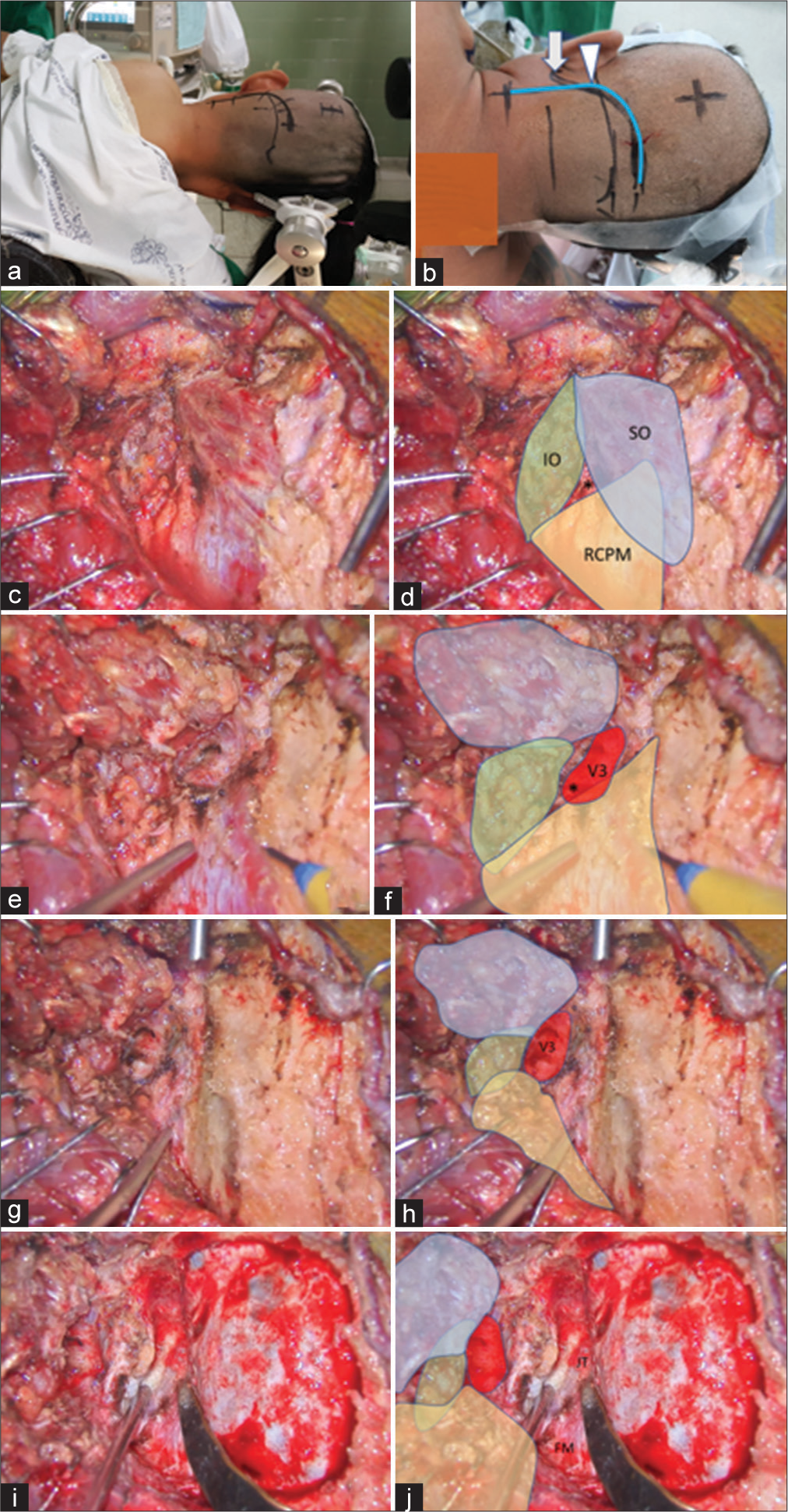
Figure 7:
Illustrative Case 2 (Patient 13). (a) Right semi-prone park bench position. (b) Skin incision (blue line) relative to the mastoid tip (arrow) and mastoid groove (arrowhead). (c-h) The steps to expose the third segment of the left vertebral artery are demonstrated, similar to Figure 1-3. The superior oblique (SO, blue color), inferior oblique (IO, green color), and rectus capitis posterior major (RCPM, yellow color) muscles; the third segment of the vertebral artery (V3, red color); and the center of the suboccipital triangle (asterisk) are shown. (I and j) The left far lateral transcondylar fossa approach.
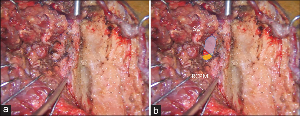
Figure 8:
Illustrative Case 2 (Patient 13). (a and b) Intraoperative findings during the left suboccipital muscle dissection and exposure for the far lateral transcondylar approach. (b) The superior oblique (SO) and rectus capitis posterior major (RCPM) muscles were elevated. The third segment of the vertebral artery (blue, red, and yellow colors) was exposed. The blue color was covered by the SO, which included the lateral 68% of the third segment of the vertebral artery. The yellow color was covered by RCPM, which included the medial 24% of the third segment of the vertebral artery. The red color was located within the center of the suboccipital triangle (asterisk).
DISCUSSION
Surgical anatomy of the V3
The relationship between the V3 and the surrounding bones was well-described in cadaveric studies by Lang and Kessler[
The relationship between the V3 and the surrounding muscles was described by Meybodi et al.[
Operative techniques for V3 exposure
Several techniques for V3 exposure were described previously. Youssef et al. suggested an interfascial dissection technique that followed the natural plane between the deep suboccipital muscle fascia, the posterior atlantooccipital membrane, and the periosteum of the C1 and C2 laminae and the lateral masses.[
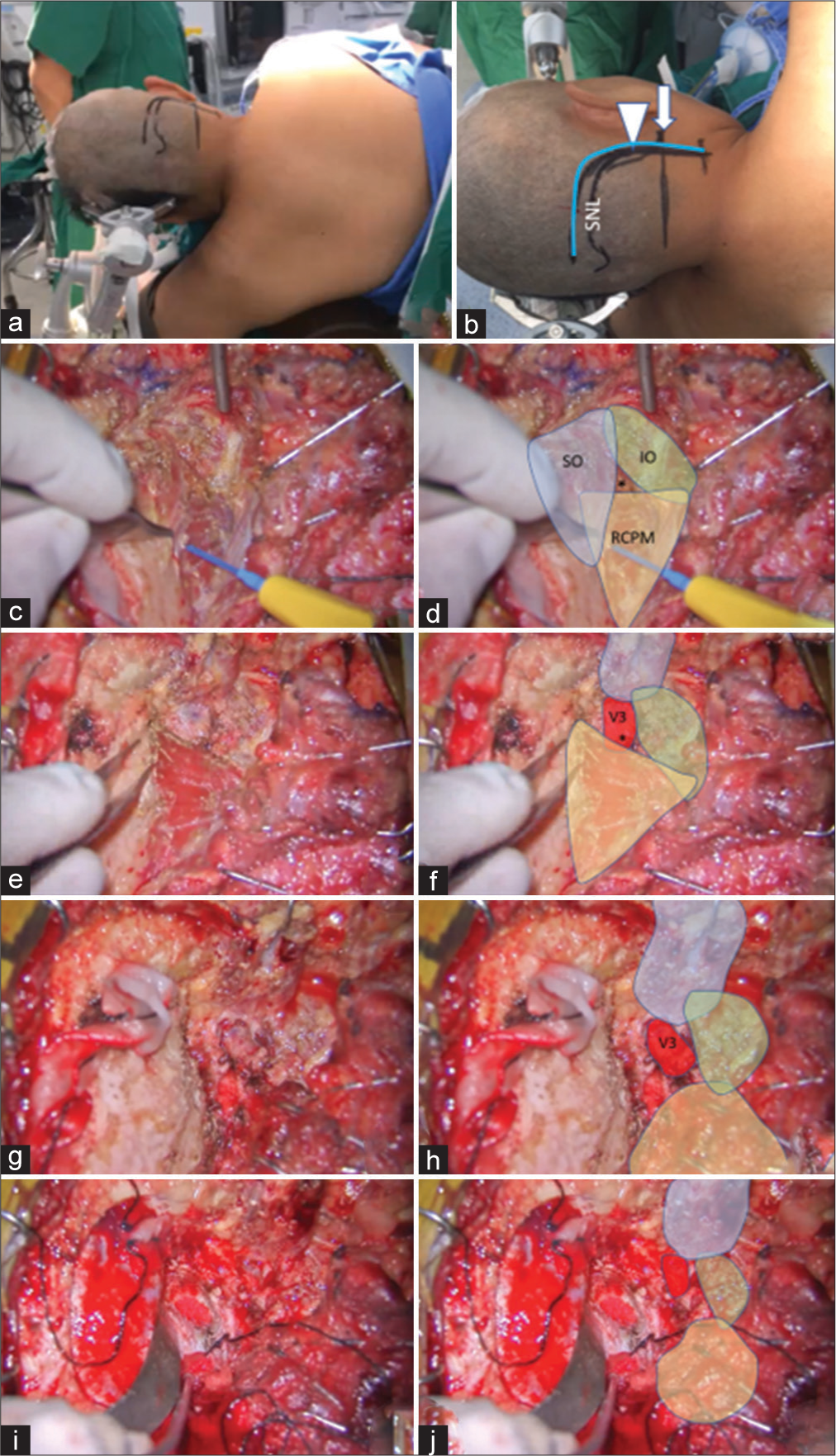
Figure 9:
Illustrative Case 3 (Patient 14). (a) Left semi-prone park bench position. (b) Skin incision (blue line) relative to the mastoid tip (arrow), mastoid groove (arrowhead), and superior nuchal line (SNL). (c-h). The steps to expose the third segment of the right vertebral artery are demonstrated, similar to Figures 1-3. The superior oblique (SO, blue color), inferior oblique (IO, green color), and rectus capitis posterior major (RCPM, yellow color) muscles; the third segment of the vertebral artery (V3, red color); and the center of the suboccipital triangle (asterisk) are shown. (i and j) Right far lateral transcondylar approach.
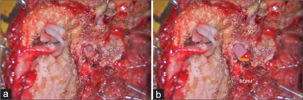
Figure 10:
Illustrative Case 3 (Patient 14). (a and b) Intraoperative findings during right suboccipital muscle dissection and exposure for the far lateral transcondylar approach. (b) The superior oblique (SO) and rectus capitis posterior major (RCPM) muscles were elevated. The third segment of the vertebral artery (blue, red, and yellow colors) was exposed. The blue color was covered by the SO, which included the lateral 68% of the third segment of the vertebral artery. The yellow color was covered by the RCPM, which included the medial 23% of the third segment of the vertebral artery. The red color was located within the center of the suboccipital triangle (asterisk).
Meybodi et al. suggested that the V3 could be localized using the distance from the atlanto-mastoid line. The V3 location is 40% of the distance from the mastoid process. However, the posterior tubercle of C1 is difficult to palpate because of the bulky muscles of the suboccipital region. Furthermore, this study was limited because of the use of cadavers and the position of the cadaveric head.[
George and Laurian also described techniques for V3 exposure, as follows. With the anterolateral approach, the tip of the C1 transverse process was identified first. The insertion of the SO was detached from the C1 transverse process and dissected superomedially above the V3. The C1 groove was identified and the VA was secured within the groove.[
Ota et al. described a transcondylar fossa approach for bilateral V3 exposure to treat complex VA aneurysms. They used a multiple-layer technique for suboccipital muscle dissection and identified the posterior arch of C1, SO, and RCPM as the landmarks for V3.[
In this study, we used the V3 exposure technique similar to the technique described by Balik and Takizawa and used the bipolar cutting method described by Tokugawa et al.[
To the best of our knowledge, all previous studies regarding the course of V3, SOT, and suboccipital muscles were performed in cadavers; we found no clinical studies.[
Limitations of study
There are several limitations to our study. First, this study was a retrospective and descriptive one. Therefore, no comparative group for an accurate evaluation of the benefits of the technique was available. Second, a relatively small number of patients were studied because the operative video during V3 exposure was only recorded in cases when OA-PICA was performed. Finally, the measurements were not intraoperatively performed at the time of surgery but were measured from the operative videos.
CONCLUSION
Most of the V3, including the V3 bulge, were located beneath the SO and the inferomedial part of V3 located within the SOT. Elevation of the SO is the most-likely step to injure the V3; this step should be performed carefully using the bipolar cutting technique. To the best of our knowledge, this is the first study to describe the identification of the V3 relative to the SOT in clinical cases.
Declaration of patient consent
Institutional Review Board (IRB) permission obtained for the study.
Financial support and sponsorship
Nil.
Conflicts of interest
There are no conflicts of interest.
Videos available on:
References
1. Ahn J, Duran M, Syldort S, Rizvi A, D’Antoni AV, Johal J. Arcuate foramen: Anatomy, embryology, nomenclature, pathology, and surgical considerations. World Neurosurg. 2018. 118: 197-202
2. Balik V, Takizawa K. Safe and bloodless exposure of the third segment of the vertebral artery: A step-by-step overview based on over 50 personal cases. Neurosurg Rev. 2019. 42: 991-7
3. Bertalanffy H, Seeger W. The dorsolateral, suboccipital, transcondylar approach to the lower clivus and anterior portion of the craniocervical junction. Neurosurgery. 1991. 29: 815-21
4. Castillo C, Viñas FC, Gutikhonda M, Diaz FG. Microsurgical anatomy of the suboccipital segment of the vertebral artery. Neurol Res. 1998. 20: 201-8
5. Cengiz SL, Cicekcibasi A, Kiresi D, Kocaogullar Y, Cicek O, Baysefer A. Anatomic and radiologic analysis of the atlantal part of the vertebral artery. J Clin Neurosci. 2009. 16: 675-8
6. de Oliveira E, Rhoton AL, Peace D. Microsurgical anatomy of the region of the foramen magnum. Surg Neurol. 1985. 24: 293-352
7. George B, Laurian C. Surgical possibilities in the third portion of the vertebral artery (above C2), Anatomical study and report of a case of anastomosis between subclavian artery and vertebral artery at C1-C2 level. Acta Neurochir Suppl (Wien). 1979. 28: 263-9
8. George B. Extracranial vertebral artery anatomy and surgery. Adv Tech Stand Neurosurg. 2002. 27: 179-216
9. Heros RC. Lateral suboccipital approach for vertebral and vertebrobasilar artery lesions. J Neurosurg. 1986. 64: 559-62
10. La Rocca G, Altieri R, Ricciardi L, Olivi A, Della Pepa GM. Anatomical study of occipital triangles: The ‘inferior’ suboccipital triangle, a useful vertebral artery landmark for safe postero-lateral skull base surgery. Acta Neurochir (Wien). 2017. 159: 1887-91
11. Lang J, Kessler B. About the suboccipital part of the vertebral artery and the neighboring bone-joint and nerve relationships. Skull Base Surg. 1991. 1: 64-72
12. Loukas M, Tubbs RS. An accessory muscle within the suboccipital triangle. Clin Anat. 2007. 20: 962-3
13. Matsushima T, Kawashima M, Masuoka J, Mineta T, Inoue T. Transcondylar fossa (supracondylar transjugular tubercle) approach: Anatomic basis for the approach, surgical procedures, and surgical experience. Skull Base. 2010. 20: 83-91
14. Matsushima T, Matsukado K, Natori Y, Inamura T, Hitotsumatsu T, Fukui M. Surgery on a saccular vertebral artery-posterior inferior cerebellar artery aneurysm via the transcondylar fossa (supracondylar transjugular tubercle) approach or the transcondylar approach: Surgical results and indications for using two different lateral skull base approaches. J Neurosurg. 2001. 95: 268-74
15. Matsushima T, Natori Y, Katsuta T, Ikezaki K, Fukui M, Rhoton AL. Microsurgical anatomy for lateral approaches to the foramen magnum with special reference to transcondylar fossa (supracondylar transjugular tubercle) approach. Skull Base Surg. 1998. 8: 119-25
16. Meybodi AT, Lawton MT, Benet A. Sequential extradural release of the V3 vertebral artery to facilitate intradural V4 vertebral artery reanastomosis: Feasibility of a novel revascularization technique. Oper Neurosurg (Hagerstown). 2017. 13: 345-51
17. Meybodi AT, Rincon-Torroella J, El-Sayed IH, Lawton MT, Benet A. Early localization of the third segment of the vertebral artery: The atlanto-mastoid line. Oper Neurosurg (Hagerstown). 2016. 12: 350-9
18. Muralimohan S, Pande A, Vasudevan MC, Ramamurthi R. Suboccipital segment of the vertebral artery: A cadaveric study. Neurol India. 2009. 57: 447-52
19. Nayak SR, Swamy R, Krishnamurthy A, Dasgupta H. Bilateral anomaly of rectus capitis posterior muscles in the suboccipital triangle and its clinical implication. Clin Ter. 2011. 162: 355-6
20. Ota N, Tanikawa R, Miyama M, Miyazaki T, Kinoshita Y, Matsukawa H. A Contralateral transcondylar fossa approach with bilateral V3 segment exposure for repairing complex vertebral artery aneurysms. World Neurosurg. 2017. 99: 340-7
21. Rhoton AL. The far-lateral approach and its transcondylar, supracondylar, and paracondylar extensions. Neurosurgery. 2000. 47: S195-209
22. Sen CN, Sekhar LN. An extreme lateral approach to intradural lesions of the cervical spine and foramen magnum. Neurosurgery. 1990. 27: 197-204
23. Sriamornrattanakul K, Akharathammachote N. The intersection between the sternocleidomastoid and splenius capitis as the anatomical landmark to facilitate occipital artery harvest: A retrospective clinical study. World Neurosurg. 2022. 157: e364-73
24. Tayebi Meybodi A, Zhao X, Borba Moreira L, Lawton MT, Lang MJ, Labib M. The inferior nuchal line as a simple landmark for identifying the vertebral artery during the retrosigmoid approach. Oper Neurosurg (Hagerstown). 2020. 18: 302-8
25. Tokugawa J, Ogura K, Yatomi K, Kudo K, Hishii M, Tanikawa R. Bipolar cutting method: Another technique for harvesting donor artery with histological investigation. Oper Neurosurg (Hagerstown). 2018. 14: 16-9
26. Ulm AJ, Quiroga M, Russo A, Russo VM, Graziano F, Velasquez A. Normal anatomical variations of the V3 segment of the vertebral artery: Surgical implications. J Neurosurg Spine. 2010. 13: 451-60
27. Wanibuchi M, Fukushima T, Zenga F, Friedman AH. Simple identification of the third segment of the extracranial vertebral artery by extreme lateral inferior transcondylar-transtubercular exposure (ELITE). Acta Neurochir (Wien). 2009. 151: 1499-503
28. Wen HT, Rhoton AL, Katsuta T, de Oliveira E. Microsurgical anatomy of the transcondylar, supracondylar, and paracondylar extensions of the far-lateral approach. J Neurosurg. 1997. 87: 555-85
29. Wongsuriyanan S, Sriamornrattanakul K. Blind-alley formation and occipital artery-posterior inferior cerebellar artery bypass for the treatment of unclippable vertebral artery aneurysms with posterior inferior cerebellar artery involvement. World Neurosurg. 2020. 138: e539-50
30. Youssef AS, Uribe JS, Ramos E, Janjua R, Thomas LB, van Loveren H. Interfascial technique for vertebral artery exposure in the suboccipital triangle: The road map. Neurosurgery. 2010. 67: 355-61