- Department of Neurosurgery, Avicenne Military Hospital of Marrakech and Mohammed V University in Rabat, Marrakech, Morocco.
DOI:10.25259/SNI_791_2020
Copyright: © 2020 Surgical Neurology International This is an open-access article distributed under the terms of the Creative Commons Attribution-Non Commercial-Share Alike 4.0 License, which allows others to remix, tweak, and build upon the work non-commercially, as long as the author is credited and the new creations are licensed under the identical terms.How to cite this article: Ali Akhaddar. HeaDax: A simple pre-surgical procedure for localizing superficial brain lesions in resource-limited environments. 22-Dec-2020;11:461
How to cite this URL: Ali Akhaddar. HeaDax: A simple pre-surgical procedure for localizing superficial brain lesions in resource-limited environments. 22-Dec-2020;11:461. Available from: https://surgicalneurologyint.com/surgicalint-articles/10486/
Date of Submission
05-Nov-2020
Date of Acceptance
05-Dec-2020
Date of Web Publication
22-Dec-2020
Abstract
Background: Intracranial convexity lesions are poorly defined by recognizable anatomical landmarks. Even in expert hands, exact localization of small subcortical lesion and its projection to the skull is sometimes unreliable and can cause potential surgical complications. In this report, a simple and handy technique for localizing superficial intracranial lesions on the scalp under computed tomography (CT)-scan guidance is described.
Methods: This technique, HeaDax, is based on using extracranial landmarks. We constructed an isosceles square triangle with three pieces of copper electrical wire and placed it on the skin scalp. Then, we took a CT-scan but without the need of the classic head reference planes (e.g., orbitomeatal or along the orbital roof).
Results: For the measurements, we need to have the intracranial lesion located on the CT slice with respect to the two landmarks which are the height and hypotenuse of the triangle. The promising preliminary results of HeaDax applied to a phantom skull model encourage us to use it successfully for our first patient presenting a right subcortial supramarginal retrorolandic cavernoma.
Conclusion: HeaDax procedure is a good alternative for localizing superficial intracranial lesions on the skin scalp under CT-scan or magnetic resonance imaging guidance. It can be used as a substitute when stereotactic and neuronavigation systems are not easily available, especially in developing countries and in resource-limited environments. HeaDax has a true potential for further developments and applications in cranial surgery.
Keywords: Computer-assisted surgery, Frameless stereotaxy, Global neurosurgery, Intracranial lesions, Localizer, Surgical planning
INTRODUCTION
Intracranial convexity lesions are poorly defined by recognizable anatomical landmarks.[
Since the birth of modern neurosurgery, many methods have already been published and used to correlate an intracranial convexity lesion seen on neuroimaging with its scalp projection.[
In this report, a simple and handy technique for localizing superficial intracranial lesions on the scalp under CT-scan guidance is described.
METHOD OF LOCALIZATION
Using a real adult human skull as a phantom head model, we tried to recreate practical pre-operative conditions and restrictions to apply our procedure. This technique required the following low-cost and commonly found materials: a permanent marker pen, a flexible ruler and square, a double-sided transparent tape, copper electrical wires, scissors, and a basic CT-scan machine.
The modus operandi is described in seven steps:
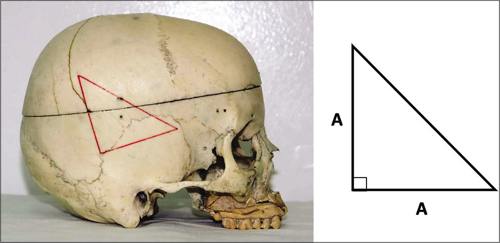
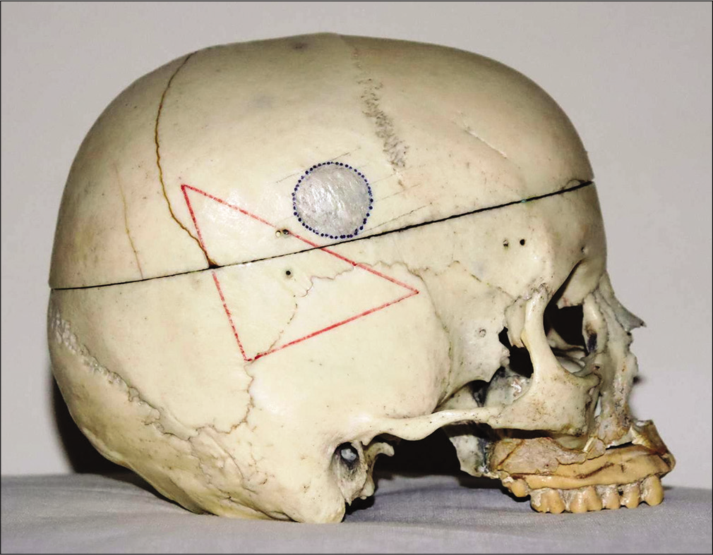
Step 1: After shaving the cranial area of interest, a right-angled isosceles lower-base triangle is drawn by a permanent marker pen on the skin scalp using a flexible ruler and square [
Step 2: Stick a double-sided transparent tape on the three sides of the triangle. Place three pieces of copper electrical wire (as radio-opaque markers) corresponding to the sides of the triangle [
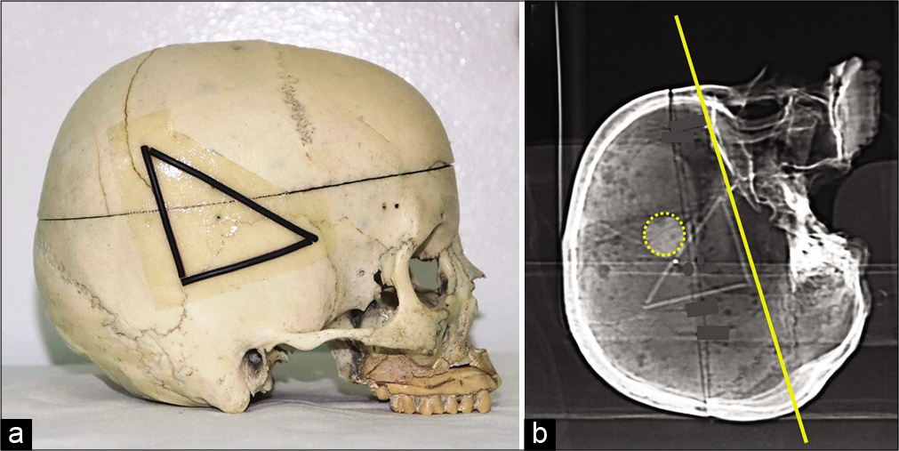
Figure 2:
A double-sided transparent tape is stuck on the three sides of the triangle. We place three pieces of copper electrical wire (as radio-opaque markers) corresponding to the sides of the triangle (a). Axial images are directly acquired on head computed tomography-scan where the reference plane (baseline on yellow) corresponds to the base of the triangle that is identified on the lateral scout view of the skull (b).
Step 3: Head CT-scan is performed for the patient. Axial images are directly acquired with the traditional volume acquisition protocol where the reference plane (baseline) corresponds to the base of the triangle that is identified on the lateral scout view of the skull provided with the CT-scan images [
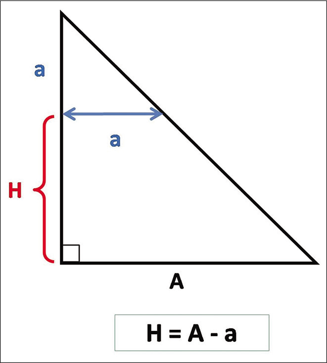
Step 4: For any axial section/slice of interest, it will be necessary to identify the height (H) of the section plane relative to the base of the triangle (baseline) using the mathematic formula [H = A–a], where (A) is the length of one side of the isosceles triangle and (a) the distance between the two markers on the corresponding axial cut [

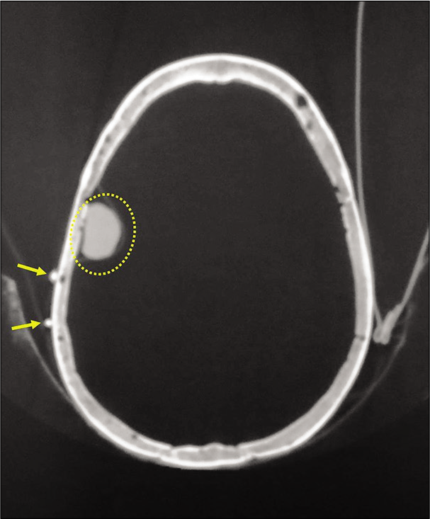
Step 5: Then, for each axial section/slice of interest, specify the anterior and posterior limits of the lesion by calculating the distance of these limits compared to one of the two radio-opaque marks [

Figure 6:
Axial computed tomography-scan. For each axial section/ slice of interest, we specify the anterior and posterior limits of the lesion by calculating the distance of these limits compared to one of the two radio-opaque marks. In the present example, the anterior and posterior limit of the lesion correspond to “d1” (29.2 mm) and “d2” (7.2 mm), respectively, compared to the anterior radio-opaque marker (double arrows).
Step 6: Finally, freehand connect the points limiting the lesion on the skin scalp, as shown in [
Step 7: The surgical approach will be at the discretion of the neurosurgeon taking into consideration his/her experience, the patient’s condition, the surgical position, as well as the volume, shape, topography, and the potential nature of the lesion.
RESULTS
The promising preliminary results of HeaDax applied to a phantom skull model encourage us to use it for our first patient presenting a right parietal cavernoma.
This 29-year-old male diagnosed 2 months early with symptomatic epilepsy and slurred speech without other neurologic findings. CT-scan and MRI showed a right 10 mm subcortial supramarginal retrorolandic cavernoma [

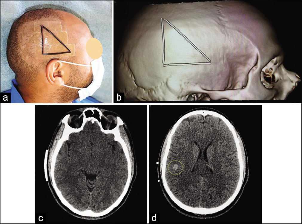
Figure 9:
Surgical preplanning. Radio-opaque scalp markers on patient’s head (a). Computed tomography-scan with superficial copper markers. Three-dimensional bone reconstruction (reformatted volume rendered) showing superficial markers on the right fronto-parieto-temporal area (b). Axial CT-scan showing the base of the triangle (baseline) (c) and the cavernoma (yellow circle) with the two copper markers (d).
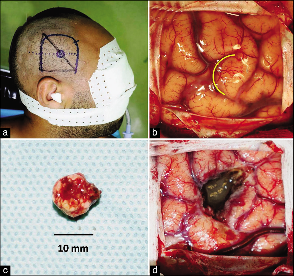
Figure 10:
Lateral view of the skull showing the projection of the cavernoma on the cranial surface relative to the marker triangle (a). Note the outline of the surgical incision. Operative view showing the sulcal entry point (yellow curved line) (b). Macroscopic appearance of the complete removed cavernoma (c). Operative view following removal of the lesion (d).
DISCUSSION
We had sought to get a simple, inexpensive, and useful method for preoperative extracranial localization of intracranial convexity lesion without the assistance of current stereotaxic or neuronavigation systems. HeaDax is a new procedure based on using classic extracranial landmarks as reported by many authors.[
Unlike other previous techniques, the variations of the head shape do not hinder the HeaDax procedure. Furthermore, the classic head reference planes (orbito-meatal or along the orbital roof) are not required.[
HeaDax method initially requires the aid of a radiology technician, but the technique is easy to learn and can be carried out by neurosurgeons alone.
With the HeaDax procedure, some limitations and sources of error should be taken into consideration such as the possibility of a mild rotation of the skull around different axes. In addition, this technique becomes less accurate for deeper subcortical lesions and those near to the vertex. In the latter situation, additional distance from the midline must be considered on coronal plane (this plane should be perpendicular to the base of the triangle/baseline) to avoid errors in measurements which may arise due to the maximum convexity of the skull vertex. In fact, this technique is not suitable for cerebellar convexity lesions because of the significant thickness of the suboccipital muscles.
Our procedure could also be used under traditional MRI guidance with the same principles as those made by CT-scan, but the markers should be compatible with the magnetic field.
The promising preliminary results of HeaDax applied to a phantom skull model encourage us to use it successfully for our first patient. Further, study of the application in real-time is happening to clearly evaluate the efficacy of our suggested technique. Besides localizing superficial brain lesions, such as tumor, hematoma, abscess, cyst, or cavernoma, this method could be used for localizing the entry point for ventricular shunt placement or any other cranial surgical procedure for convexity lesions requiring precision (e.g., burr hall for chronic subdural hematoma or arachnoid cyst, bone flap for acute traumatic hematomas, and craniectomy for skull bone lesion). This is a low-cost and easy technique that can be quickly learned and performed before every surgery. It helps the surgeon to plane a safe craniotomy and lesionectomy.
CONCLUSION
The HeaDax procedure is a good alternative for localizing superficial intracranial lesions on the skin scalp under CT-scan or MRI guidance. This technique is simple, practical, noninvasive, and inexpensive. It can be used as a substitute when stereotactic and neuronavigation systems are not easily available, especially in developing countries and in resource-limited environments. HeaDax has a true potential for further developments and applications in cranial surgery.
Declaration of patient consent
The authors certify that they have obtained all appropriate patient consent.
Financial support and sponsorship
Publication of this article was made possible by the James I. and Carolyn R. Ausman Educational Foundation.
Conflicts of interest
There are no conflicts of interest.
Acknowledgments
The author thanks Pr. El Mehdi Atmane and Dr. Nabil Hammoune from Department of Radiology (Avicenne Military Hospital) as well as Ms. Hiba Akhaddar (School of Science and Engineering, Al Akhawayn University of Ifrane) for their valuable suggestions in the development of this technical procedure.
References
1. Akhaddar A, Akhaddar H. A new learning approach for identifying cortical brain areas around the central sulcus using the name of Allah. Surg Neurol Int. 2019. 10: 244
2. Akhaddar A, Boucetta M.editors. La Neuronavigation à L’aide du Microscope Robotisé MKM®, L’expérience Marocaine, Saarbrucken, Germany. Editions Universitaires Européennes;. 2011. p. 96
3. Ananthanandorn A. Calvarial freehand entry point localization using virtual orbito-meatal (OM) computerized tomography (CT) study plane as reference: A case report. J Med Assoc Thai. 2018. 101: S159-63
4. Bertalanffy H, Bechtel S, Seeger W. Regional exposure of cerebral convexity lesions. Neurochirurgia (Stuttg). 1993. 36: 81-6
5. Eftekhar B. A smartphone app to assist scalp localization of superficial supratentorial lesions-technical note. World Neurosurg. 2016. 85: 359-63
6. Fernandes YB, Borges G, Ramina R, Carelli EF. Double-checked preoperative localization of brain lesions. Arq Neuropsiquiatr. 2003. 61: 552-4
7. Gumprecht HK, Widenka DC, Lumenta CB. Brain lab vector vision neuronavigation system: Technology and clinical experiences in 131 cases. Neurosurgery. 1999. 44: 97-105
8. Hirschberg H. Localization of brain tumors with a simple scalp-mounted fiducial device, Technical note. J Neurosurg. 1989. 70: 280-1
9. Ikeda A, Ito K, Matsuzawa K, Tanaka K, Miyazaki Y, Yamamoto I. Craniotomy for lesions in the cerebral convexity; how to precisely localize the lesions with conventional CT slices. No Shinkei Geka. 1992. 20: 875-81
10. Mayfrank L, Bertalanffy H, Spetzger U, Klein HM, Gilsbach JM. Ultrasound-guided craniotomy for minimally invasive exposure of cerebral convexity lesions. Acta Neurochir (Wien). 1994. 131: 270-3
11. Nayak PK, Dutta J. Craniomapper for accurate localization of lesion during craniotomy: How much benefit does it have over anatomical marking? Report of two cases. J Neurosci Rural Pract. 2014. 5: 202-3
12. O’Leary DH, Lavyne MH. Localization of vertex lesions seen on CT scan. J Neurosurg. 1978. 49: 71-4
13. Quiñones-Hinojosa A, Ware ML, Sanai N, McDermott MW. Assessment of image guided accuracy in a skull model: Comparison of frameless stereotaxy techniques vs. frame-based localization. J Neurooncol. 2006. 76: 65-70
14. Raabe A, Fichtner J, Raabe A.editors. Convexity craniotomies. The Craniotomy Atlas. Germany: Thieme Publishing Group; 2019. p. 69-79
15. Spincemaille GH, Versteege CW, Blaauw G. Computed tomography-guided scalp marking of cerebral surface lesions; an alternative to stereotaxis for small convexity lesions. Eur J Radiol. 1990. 11: 143-4
16. Spiriev T, Nakov V, Laleva L, Tzekov C. OsiriX software as a preoperative planning tool in cranial neurosurgery: A step-by-step guide for neurosurgical residents. Surg Neurol Int. 2017. 8: 241
17. Stieglitz LH, Fichtner J, Andres R, Schucht P, Krähenbühl AK, Raabe A. The silent loss of neuronavigation accuracy: A systematic retrospective analysis of factors influencing the mismatch of frameless stereotactic systems in cranial neurosurgery. Neurosurgery. 2013. 72: 796-807