- Department of Neurosurgery, Maastricht University Medical Center+, P. Debyelaan 25, 6229 HX Maastricht, The Netherlands
- Department of Medical Information Technology, Maastricht University Medical Center+, P. Debyelaan 25, 6229 HX Maastricht, The Netherlands
- Department of Neurology, Maastricht University Medical Center+, P. Debyelaan 25, 6229 HX Maastricht, The Netherlands
- Department of Neurosurgery, Ondokuz Mayis University Hospital, Atakum-Samsun 55139, Samsun, Turkey
Correspondence Address:
Onur Alptekin, Felix S. Gubler, Felix S. Gubler
Department of Neurosurgery, Maastricht University Medical Center+, P. Debyelaan 25, 6229 HX Maastricht, The Netherlands
DOI:10.25259/SNI-88-2019
Copyright: © 2019 Surgical Neurology International This is an open-access article distributed under the terms of the Creative Commons Attribution-Non Commercial-Share Alike 4.0 License, which allows others to remix, tweak, and build upon the work non-commercially, as long as the author is credited and the new creations are licensed under the identical terms.How to cite this article: Onur Alptekin, Felix S. Gubler, Linda Ackermans, Pieter L. Kubben, Mark L. Kuijf, Ersoy Kocabicak, Yasin Temel. Stereotactic accuracy and frame mounting: A phantom study. 24-Apr-2019;10:67
How to cite this URL: Onur Alptekin, Felix S. Gubler, Linda Ackermans, Pieter L. Kubben, Mark L. Kuijf, Ersoy Kocabicak, Yasin Temel. Stereotactic accuracy and frame mounting: A phantom study. 24-Apr-2019;10:67. Available from: http://surgicalneurologyint.com/surgicalint-articles/9287/
Date of Submission
21-Oct-2018
Date of Acceptance
21-Nov-2018
Date of Web Publication
24-Apr-2019
Abstract
Background:Frame mounting is considered one of the most critical steps in stereotactic neurosurgery. In routine clinical practice, the aim is to mount the frame as symmetrical as possible, parallel to Reid’s line. However, sometimes, the frame is mounted asymmetrically often due to patient-related reasons.
Methods:In this study, we addressed the question whether an asymmetrically mounted frame influences the accuracy of stereotactic electrode implantation. A Citrullus lanatus was used for this study. After a magnetic resonance imaging scan, symmetric and asymmetric mounting of the frame, which could occur in clinical scenarios, was performed with computed tomography (CT). Three different stereotactic software packages were used to analyze the results. In addition, manual calculations were performed by two different observers.
Results:Our results show that an asymmetrically mounted frame (deviated, tilted, or rotated) does not affect the accuracy in the mediolateral axis (X-coordinate) or the anteroposterior axis (Y-coordinate). However, it can lead to a clinically relevant error in the superoinferior axis (Z-coordinate). This error was largest with manual calculations.
Conclusion:These results suggest that asymmetrical frame mounting can lead to stereotactic inaccuracy in the superoinferior axis (Z coordinate).
Keywords: Accuracy, deep brain stimulation, frame, mounting, phantom
INTRODUCTION
Stereotactic neurosurgery is the technique for locating targets of surgical interest within the brain relative to an external frame of reference.[
To reach a high level of precision in stereotactic surgeries, there are several sources of potential error which should be taken into account. Besides the mechanical errors of the stereotactic system itself, errors can occur due to imaging protocols and techniques and stereotactic planning software.
An important step in stereotaxy is mounting the frame on the head of the patient. The aim is to mount the frame as symmetrical as possible parallel to Reid’s line and/or Glabella-Inion line. However, an asymmetrically mounted frame is an often seen condition, mostly due to patient-related reasons such as severe tremor, dystonia, or anxiousness. The question arises whether an asymmetrically mounted frame leads to stereotactic inaccuracy, and if yes, in which planes and to which extent?
In this study, we addressed these questions. We have performed a phantom study using a Citrullus lanatus (watermelon). After mounting the frame in several potential clinical scenarios, magnetic resonance imaging (MRI) and stereotactical computed tomography (CT) were obtained. Subsequently, image fusion was performed using three commercially available stereotactic planning software systems. For comparison reasons, we also obtained manual calculations.
MATERIALS AND METHODS
Phantom
We decided to use a phantom with natural properties, to obtain clear CT and MRI images. In this respect, we have chosen a C. lanatus (watermelon) with a form as close as possible to the human head. The rigid rind structure of a C. lanatus, with some reinforcement, was also sufficient to resist against the pressure that frame screws generate [
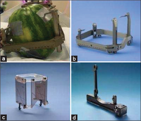
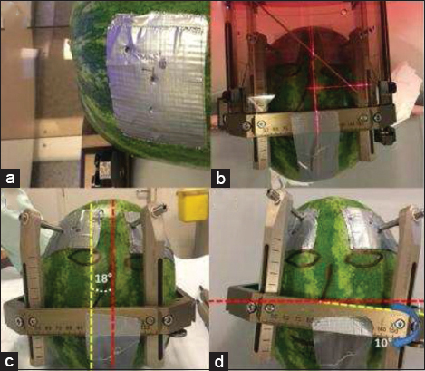
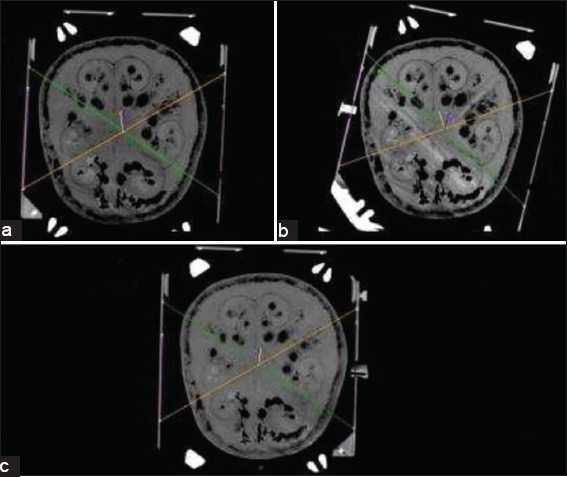
Figure 2
(a) Duct tape to increase the strength of the phantoms peel at the frame screws. (b) Symmetrically mounted for scenario 1. (c) An 18° rotational deviated mounting. The angle between the two vertical midlines, yellow (frame) and red (phantom), related to the rotational deviation is highlighted. (d) A 10° lateral tilt. The angle between two horizontal midlines, yellow (frame) and red (phantom), related to the lateral tilt is also highlighted.
The deviations and tilts were not too exaggerated to be able to mimic more or less a potential clinical situation. One specific segment, which was the deepest contact of the electrode (Medtronic 3389, Minneapolis) on the MRI images, was defined as the target for all three CT scans.
Stereotactic frame
A Leksell (Elekta, Stockholm, Sweden) Stereotactic G-frame was used during this study [
DBS lead implantation
A Medtronic 3389–28 (Medtronic, Minneapolis, USA) DBS lead was chosen for this study [
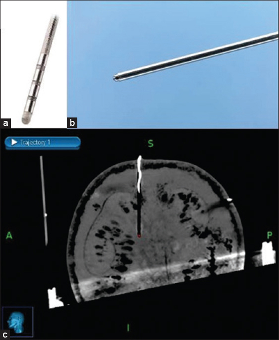
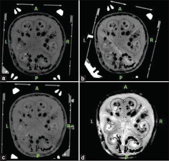
The target was defined as the deepest contact of the DBS electrode as seen on the MRI. The center of the circle with black contrast which is the artifact of DBS electrode was chosen as the target for all three scenarios [
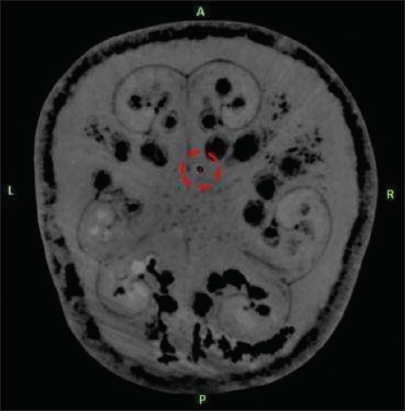
Figure 4
The second deepest computed tomography slice on which that deep brain stimulation electrode was clearly visible is shown in
Imaging and image processing
We performed a T2-weighted MRI scan to get nonstereotactic MR images of the lead implanted phantom. A 1.5 Tesla (T), Philips Ingenia (Philips, Eindhoven, the Netherlands) MRI machine was used in this phase. Slice thickness for T2-weighted MR images was 2 mm with no angulation. After mounting the frame, each time we performed a stereotactic CT scan for the three different frame-mounted scenarios [
The targeting phases were performed both computer-based and manually. For the computer-based analyses, we used three different planning stations:
Medtronic Framelink version 5.4.1 (Medtronic, Minneapolis, USA), Medtronic Cranial Software (Medtronic, Minneapolis, USA), Brainlab iPlan (Brainlab, Feldkirchen, Germany).
Since we had three different stereotactic CT scans for three different scenarios, MRI T2 series were chosen as registration series and all three CT series were merged with T2 axial images [
For each mounting scenario, we registered the related stereotactic CT series to Framelink 5.4.1, Medtronic Cranial and Brainlab iPlan software. The stereotactic coordinates generated for the target point by three planning stations for each three frame mounting scenario were recorded. The targeting was also performed manually using the method which is defined for N-Localizers.[
RESULTS
For the rotational deviation scenario, the deviation angle was measured as 18° [
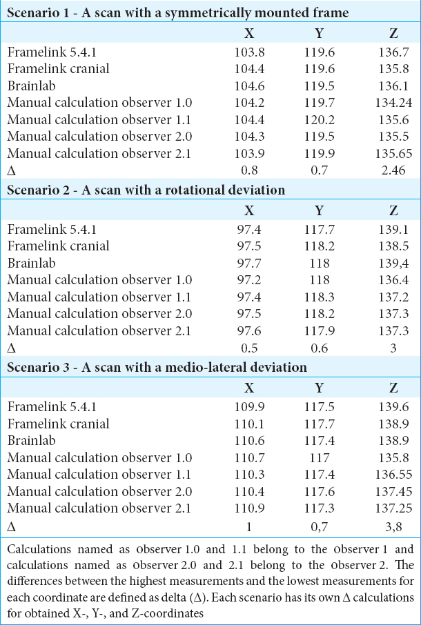
Scenario 1 – A scan with a symmetrically mounted frame
For scenario 1, the absolute difference between the highest (Brainlab iPlan – 104.6 mm) and the lowest (Framelink 5.4.1 mm–103.8 mm) measurements for X-coordinate was 0.8 mm. The absolute difference between the highest (Manual Calculation – 120.2 mm) and the lowest (Brainlab Iplan – 119.5 mm) measurements for Y-coordinate in scenario 1 was 0.7 mm. For the Z-coordinate, the absolute difference between the highest (Framelink 5.4.1 mm–136.7 mm) and the lowest (manual Calculation – 134.24 mm) measurements in scenario 1 was 2.46 mm.
Scenario 2 – A scan with a rotational deviated mounting
For scenario 2, the absolute difference between the highest (Brainlab Iplan – 97.7 mm) and the lowest (manual calculation – 97.2 mm) measurements for X-coordinate was 0.5 mm. The absolute difference between the highest (Manual calculation – 118.3 mm) and the lowest (Framelink 5.4.1 mm–117.7 mm) measurements for Y-coordinate in scenario 2 was 0.6 mm. For the Z-coordinate, the absolute difference between the highest (Brainlab iPlan – 139.4 mm) and the lowest (manual calculation – 136.4 mm) measurements in scenario 2 was 3 mm.
Scenario 3 – A scan with a lateral tilted mounting
For scenario 3, the absolute difference between the highest (manual calculation – 110.9 mm) and the lowest (framelink 5.4.1 mm – 109.9 mm) measurements for X-coordinate was 1.0 mm. The absolute difference between the highest (medtronic cranial – 117.7 mm) and the lowest (manual calculation – 117 mm) measurements for Y-coordinate in scenario 3 was 0.7 mm. For the Z-coordinate, the absolute difference between the highest (Framelink 5.4.1 mm–139.6 mm) and the lowest (manual calculation – 135.8 mm) measurements scenario 3 was 3.8 mm.
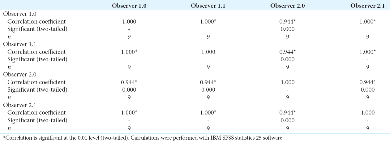
For the values obtained through manual calculations from all three scenarios, we calculated the intra- and inter-observer reliability using Kendall’s Coefficient of Concordance (W). All the W values in between observers and their observations were above 0.94 [
DISCUSSION
Here, we addressed the question whether a clinically relevant asymmetrical mounting of the frame will result in stereotactic inaccuracy and found that a rotationally deviated frame mounting and laterally tilted frame mounting will not affect the accuracy in the mediolateral axis/X-coordinate or anteroposterior axis/Y-coordinate but can lead to an inaccuracy in the superoinferior axis/Z-coordinate.
For the mediolateral axis/X-coordinate, the mean absolute error in this study was 0.76 mm (standard deviation [SD]: ±0.14). An earlier study found that the mean error of targeting using frame-based systems in the mediolateral axis/X-coordinate was 1.0 mm (SD ± 0.7).[
If we divide the results in software- and manual-calculated parameters, then the mean absolute error of the Z-coordinates obtained from the software is actually within the range reported in the literature (>1.3 mm SD ± 0.6). Due to the contribution of manual calculation technique to the mean absolute error calculations for all three data sets, the mean absolute error results appear higher than the values reported in literature. With respect to the results of our experiment and reported errors in literature, we suggest that manual calculations can lead to an inaccuracy of >1.3 mm in the superoinferior axis/Z-coordinate. Moreover, in the scenario of a deviated mounted frame, these inaccuracies increase.
The accuracy of stereotactic techniques and systems has been investigated for a long time. One study has questioned geometric accuracy of three-dimensional (3D) coordinates of the Leksell stereotactic frame in 1.5 T and 3.0 T MRI with different fixation screw materials.[
Nowadays, new technologies are still being developed by manufacturers to achieve the perfect accuracy in another stereotactic technique which is called frameless technique. The accuracy comparison between frame-based and frameless techniques had also been questioned and published.[
For the superoinferior/Z-axis coordinates, the highest inaccuracy for all three experiments is from the manual calculation technique. Since the manual calculation method is an observer-based targeting method, we obtained the manual-calculated coordinates from two independent observers and these two observers performed their manual calculations twice for each scenario. The intra- and inter-observer reliabilities we achieved were very high which led us to confirm that the source of deviation achieved from the superoinferior/Z-axis is not related to observer measurements.
In another study, it was advised to ensure that the axes of the frame are in line with those of the scanner when manual calculation methods are considered for targeting. According to the same study, with this particular attention, frame geometry is reproduced accurately on a cross-sectional imaging.[
In this study, all CT images were obtained with respect to the alignment of the scanner axis and frame axes. Since the reference or registration image series were T2-weighted nonstereotactic series, the alignment of the CT scan could have been changed after the image fusion process. The manual targeting calculations in this study were performed on these merged stereotactic images using the measurement tools of Medtronic Cranial (Medtronic, Minneapolis, USA) software. We also believe that this difference could also arise with respect to the sensitivity difference between computer-based algorithms designed for auto-detection of fiducials and the direct/manual registration performed by the user.
When we compare the clinical applications of stereotactic planning software in DBS procedures and the design of this study, another difference arises through registration series perspective. In clinical applications of stereotactic planning software, CT series are commonly used as registration series.[
In the clinical applications of the stereotactic software, the systems require some anatomical important reference points to be registered from the radiological images manually by the user. These reference points are required for the definition of anterior commissure (AC), posterior commissure (PC), and the mid-sagittal plane (MSP).[
CONCLUSION
In stereotactic neurosurgical procedures, the superoinferior axis (Z-coordinate) is susceptible for inaccuracy when manual calculations are applied and increase with an asymmetrical-mounted stereotactic frame. Furthermore, our findings suggest that using a stereotactic scan as the registration series can reduce inaccuracies when compared to nonstereotactic scans.
Financial support and sponsorship
Nil.
Conflicts of interest
There are no conflicts of interest.
Acknowledgement
The authors kindly acknowledge our CT and MRI collaborators.
References
1. Bot M, van den Munckhof P, Bakay R, Sierens D, Stebbins G, Verhagen Metman L. Analysis of stereotactic accuracy in patients undergoing deep brain stimulation using nexframe and the leksell frame. Stereotact Funct Neurosurg. 2015. 93: 316-25
2. Maciunas RJ, Galloway RL, Latimer JW. The application accuracy of stereotactic frames. Neurosurgery. 1994. 35: 682-94
3. Mirzadeh Z, Chapple K, Lambert M, Dhall R, Ponce FA. Validation of CT-MRI fusion for intraoperative assessment of stereotactic accuracy in DBS surgery. Mov Disord. 2014. 29: 1788-95
4. Nakazawa H, Mori Y, Yamamuro O, Komori M, Shibamoto Y, Uchiyama Y. Geometric accuracy of 3D coordinates of the leksell stereotactic skull frame in 1.5 tesla- and 3.0 tesla-magnetic resonance imaging:A comparison of three different fixation screw materials. J Radiat Res. 2014. 55: 1184-91
5. Rabie A, Verhagen Metman L, Slavin KV. Using “Functional” target coordinates of the subthalamic nucleus to assess the indirect and direct methods of the preoperative planning:Do the anatomical and functional targets coincide?. Brain Sci. 2016. 6: e65-
6. Schaltenbrand G.editorsAtlas for Stereotaxy of the Human Brain. Chicago: Georg Thieme Publishers; 1977. p.
7. Sharan AD, Andrews DW. Stereotactic frames:Technical considerations. Neurol Dis Ther. 2003. 58: 11-20
8. Sharma M, Deogaonkar M. Accuracy and safety of targeting using intraoperative “O-arm” during placement of deep brain stimulation electrodes without electrophysiological recordings. J Clin Neurosci. 2016. 27: 80-6
9. Sharma M, Rhiew R, Deogaonkar M, Rezai A, Boulis N. Accuracy and precision of targeting using frameless stereotactic system in deep brain stimulator implantation surgery. Neurol India. 2014. 62: 503-9
10. Slavin KV, Anderson GJ, Burchiel KJ. Comparison of three techniques for calculation of target coordinates in functional stereotactic procedures. Stereotact Funct Neurosurg. 1999. 72: 192-5
11. Smeets AY, Ackermans L, Oosterloo M, Kuijf ML, van Overbeeke JJ, Visser-Vandewalle V. Modified cement-based fixation of the deep brain stimulation electrode. Stereotact Funct Neurosurg. 2015. 93: 67-
12. Zrinzo L. Pitfalls in precision stereotactic surgery. Surg Neurol Int. 2012. 3: S53-61